
CAD Dojo
05: Keycap
Sun 17 May 2020
Background
A project I've wanted to do for a while is to create my own 3d-printed mechanical keyboard, including designing and making my own switches.
This isn't that, but I'm getting my feet wet by designing something that is at least related to designing a keyswitch.
Goal
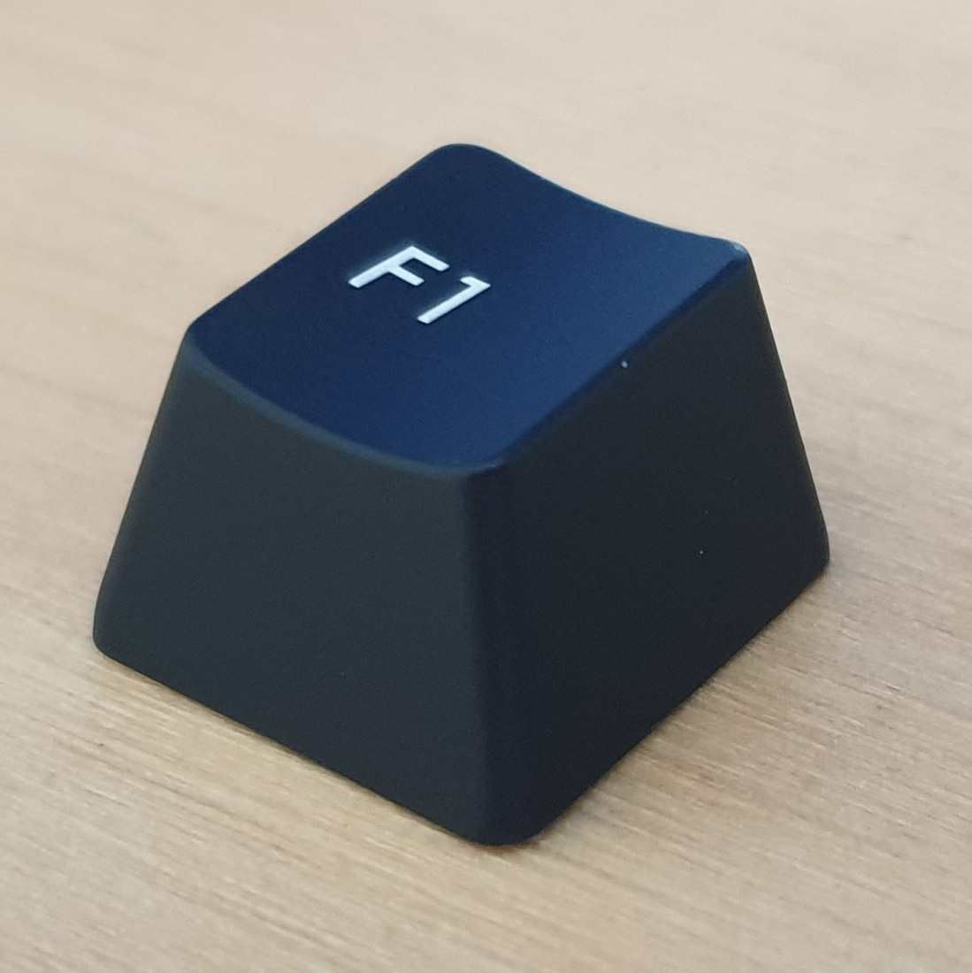
Create a CAD model for a keyboard cap compatible with Cherry MX switches.
I would have liked to have 3d printed it to see if it fit, but unfortunately my printer is out of action at the moment while I await delivery of a new hot-end.
Design
To the casual observer, a keycap is basically just a hollow cube, but closer inspection reveals that the sides are sloped at 3 different angles, and the top is both sloping and has a concave curve.
I started by drawing a shape to provide the angles for the front, back and top and padded it out to a solid in FreeCAD's Part Design workbench. Next I made a sketch of the angles for the sides and cut them out with a Pocket. Everything here is deliberately design 1mm under-size so that after the Thickness tool is applied, it comes out the correct size.
The concave shape on the top of the key is easily modelled by cutting out a section of a cylinder (i.e. draw a circle/arc, and Pocket it out), but unfortunately we don't have a reference surface perpendicular to the top of the key. In the scraper project I solved this by creating a "bodge pad" to provide a reference surface, but for this one I did it the correct way: with a datum plane.
I created the datum plane based off the flat surface on top of the key, and adjusted it to where I wanted by setting the "pitch" angle to 90°. That was easier than I expected, I think the datum plane UI looks more intimidating than it really is.
With datum plane in place, we can simply make a sketch of an arc and Pocket it into the part.
I filleted the vertical edges of the keys and hollowed out the inside using the Part Design Thickness tool. This tool is a bit hit-and-miss, in my experience. Sometimes it works fine and sometimes it gives confusing errors, with no apparent rhyme or reason.
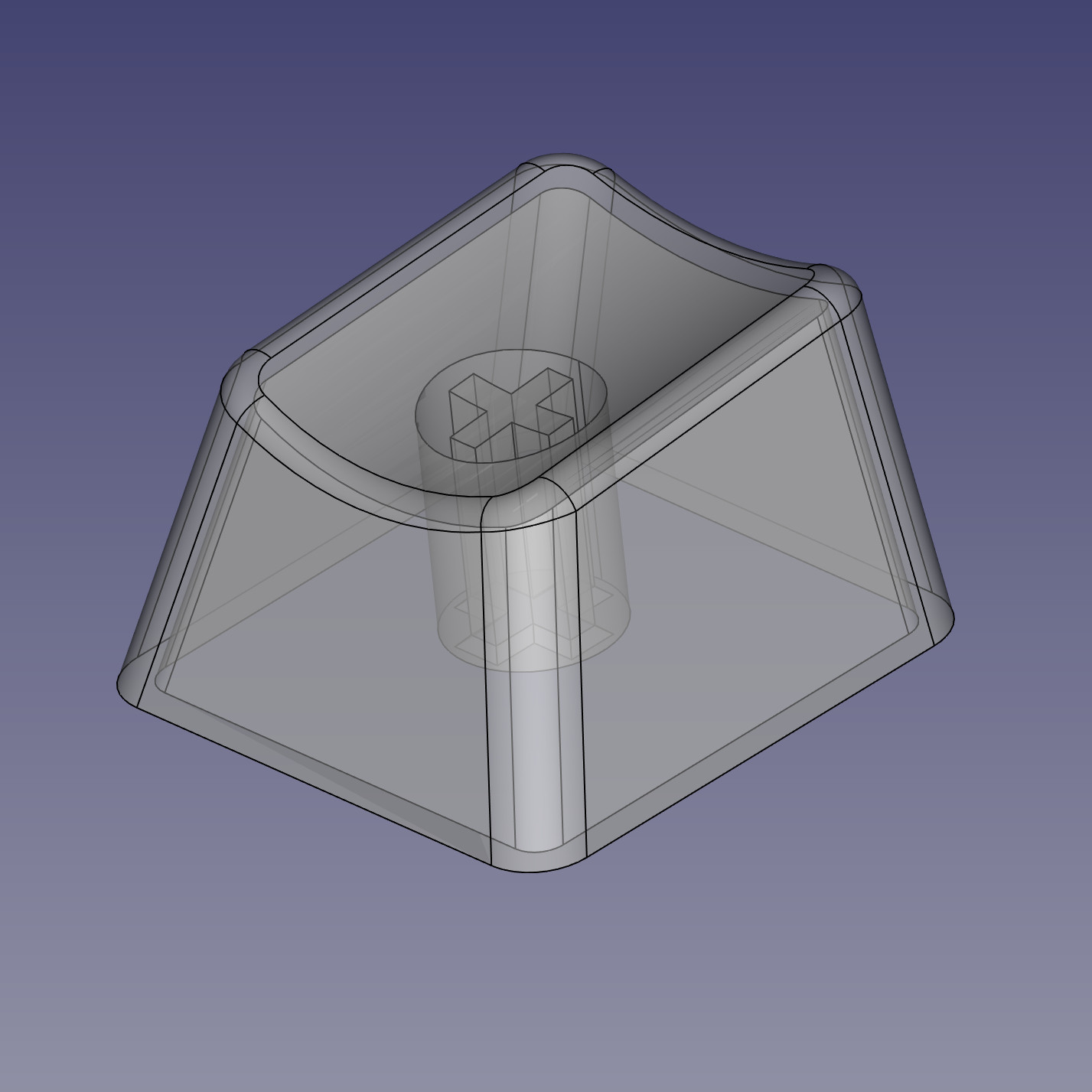
The last thing we need is a cross-shaped holder inside the key to hold it onto the keyswitch. This is a simple pad on the X/Y plane, offset by +1mm in the Z axis. We're lucky enough here that the flat top of the pad can be compeletely contained within the solid material on the top face of the key. If the pad were too wide, then the centre of it would stick out the top before the sides had even reached the bottom. I find that this is a relatively common problem when modelling complex objects and don't yet have a good general-purpose solution.
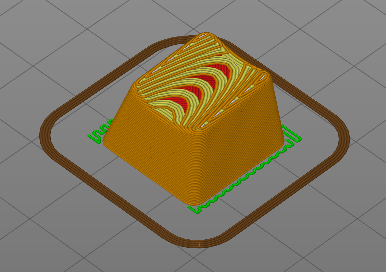
I put the part in PrusaSlicer, even though my printer is not working, just to see what it would look like.
I'm pretty confident that this would print OK, although the tiny piece of support material (green is support material) up the inside of the cross shape might be annoying to remove.
The sliced view is quite a good way to visualise the contours of the top surface.
Evaluation
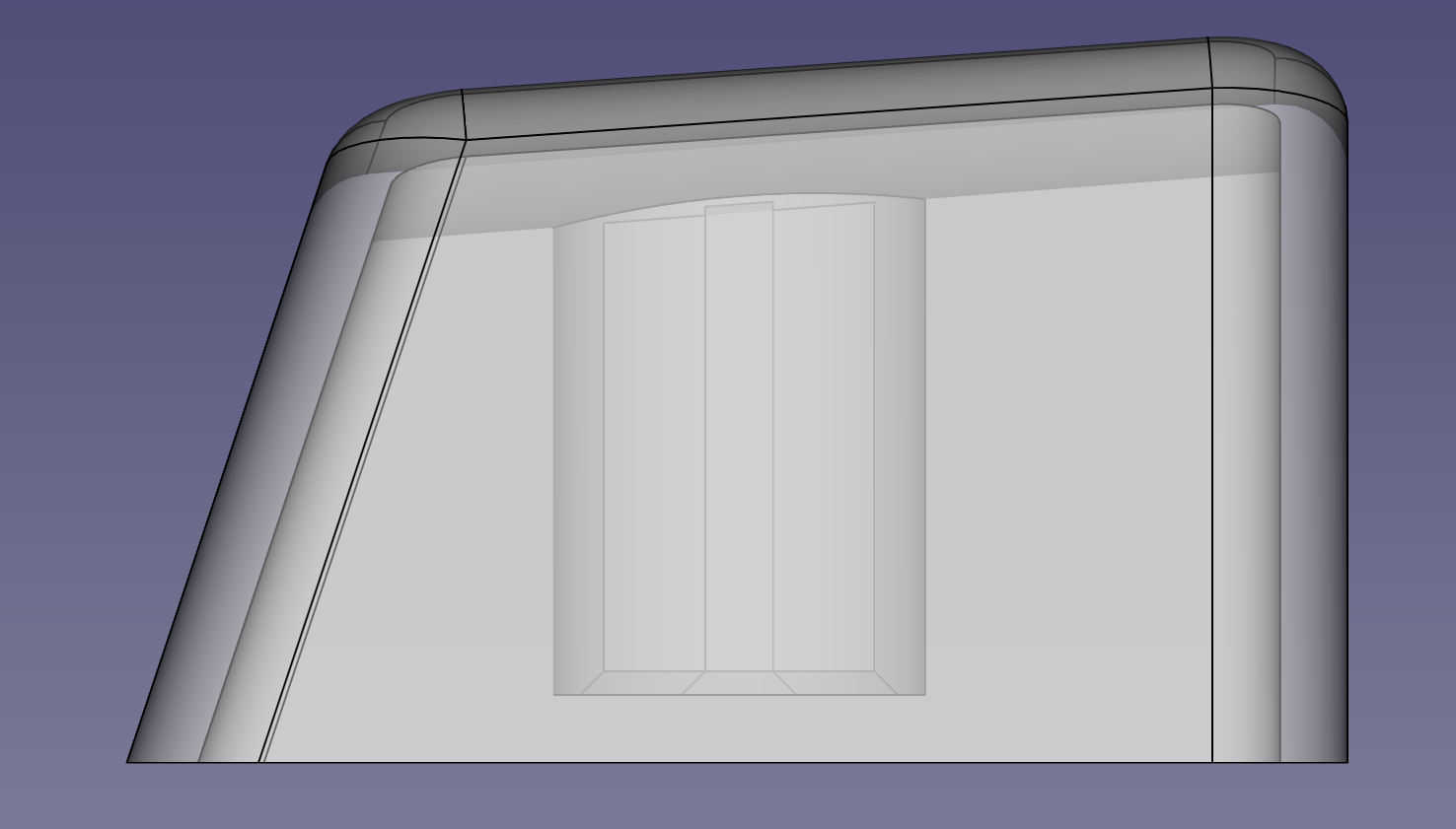
The edges on the top face of the model have too large a radius on them compared to the key I was trying to copy. This is a consequence of using the Part Design Thickness tool. I did try using the "Intersection" mode instead of "Arc" mode but it caused an error and couldn't produce a shape (classic FreeCAD). I don't know what would be the best way to model this part with sharper edges. Possibly defer creation of the final shape on top until after the Thickness operation?
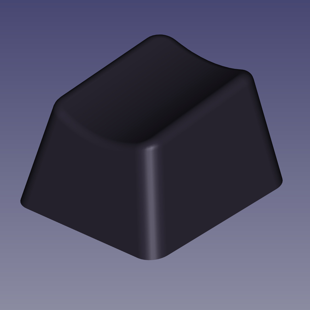
Apart from that, I think the model is adequate.