Just an update on the keyboard switch project. I've built the new 10-way testing machine, ran a (somewhat inconclusive) test to work out the best thickness for the leaf springs, and thought a bit on how I'm going to design the actual keyboard.
Here's a video of operating the new testing machine, including usage of the CLI tool for controlling it:
I normally type faster than that but I was holding the camera with one hand.
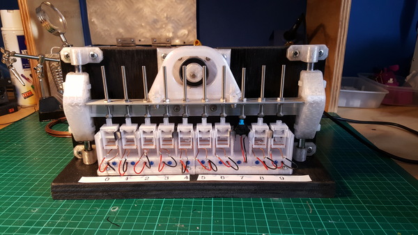
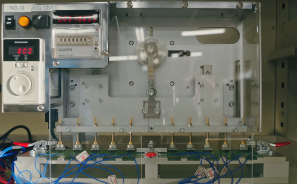
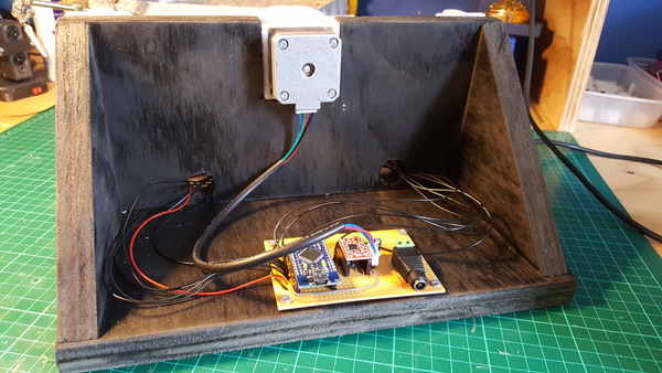
New tester
It is modelled after this one which I screenshotted from the Linus Tech Tips tour of the Omron factory:
Mechanical
Rather than use a crank to convert the motor rotation into linear motion, I thought I'd go for something a little more exotic. I browsed through the 507 Mechanical Movements website and settled on number 90. It uses a rotating cam to slide a slotted "yoke" back and forth. Advantages over a crank are that it needs fewer bearings and takes up less space in the direction of travel. But mainly it is just more unusual.
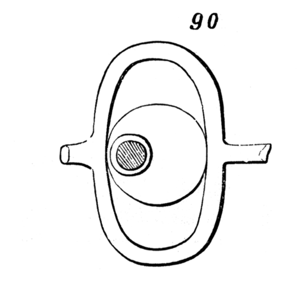
(Aside: I tried to copy the animated GIF from 507movements.com, but found that it is actually not a GIF, it is generated at runtime with JavaScript!)
The stepper motor, linear rods, and linear bearings are from my first 3d printer. I can't remember where the roller bearing is from, I found it in my tub of bearings. It doesn't appear to have been used much, so it either came out of something that was very clean, or it was a spare. It is marked "6002RS".
I managed to put together almost the entire machine for free, because I already had suitable parts and materials on hand. The only thing I had to buy was the stainless M4 nuts and bolts, which set me back almost £4. It appears that I substantially overestimated how long I'd need them to be, but no problem.
I made the classic DIY mistake of putting everything too close together without regard for the fastener placement, so it's quite annoying to work on if I need to remove or modify any parts.
Electronics
To avoid the mess of jumper wires running everywhere like on the previous tester, I put the Arduino, stepper driver, and DC barrel jack on a piece of stripboard:
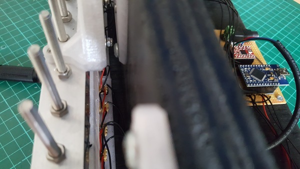
At the front, each switch needs to have a connection to an Arduino signal pin, ground, and +5v for the LED, and needs a resistor and LED. I wired these up on tiny bits of stripboard, with 6x3 holes. I think this was superior to wiring it all up with loose wires, but still a bit messy. Fortunately it's all hidden and not very easy to see:
The only reason this machine uses a stepper motor instead of a DC motor is because it is the most convenient motor I had lying around. I would have preferred to use a 12V DC motor with integrated gearbox, but not badly enough to be worth paying for one (or, worse, waiting for it to arrive).
Obviously we want to run the stepper motor as fast as possible, but a problem with stepper motors is that they lose torque as they gain speed. At 900 rpm, I have occasional trouble with the stepper motor stalling, and since I'm using an A4988 driver instead of a Trinamic one, I don't get any notification that the motor is stalled, and it just sits there buzzing until I manually intervene. This can be solved by running it slower, but on balance I think I am still winning by running it fast and checking on it periodically: the time wasted not pressing switches while stalled is made up for by the amount of extra presses while not stalled. I am already running it with the A4988 set to the highest current setting.
One great benefit of using a stepper motor is that we get precise positioning information for free. (Although, we'd also get this from a DC motor with an integrated rotary encoder, like I used on the PiKon telescope mount). Normally you need to "home" a stepper motor to work out where it is before using it. For the switch tester I don't actually need a precise absolute position, I just need the offset to be the same each revolution, so my solution is to manually move the system to roughly top-dead-centre before starting it running. You could index the position automatically any number of different ways, but manually homing it is good enough for me.
Software
The Arduino code implements a serial CLI for controlling the machine. This just lets the PC turn the motor on/off, and change the speed, and is used via a monitor program which lets the user start/stop the motors, start/stop data logging, change the speed, and show graphs of the data with gnuplot, as shown in the video above.
I first tried to drive the stepper motor with AccelStepper, but it has the problem that you need to call it frequently enough for it to toggle the step pin on and off, and this becomes a problem if the CPU is busy doing serial communication. If we miss a step, the motor stalls. No good.
I eventually implemented the stepper motor control by using the TimerOne library to trigger a timer interrupt, and then toggle the step pin and increment the step count in the interrupt handler. To accelerate the motor, we just start the timer at a low frequency and increase it until we're at the target speed. I wondered if it would be possible to use the AVR's hardware timers to both produce the square wave to toggle the step pin and keep count of how many steps have been done. It is easy to generate the square wave using Arduino's tone() function. Graham said it would be possible to count the number of steps by wiring the output of the step pin into an input pin and using the input pin as the clock source for a second timer configured to count up to 200 and then reset to 0, which would be a cool way to do it, but not really necessary at the low-ish frequencies involved (6000 Hz for 900 rpm).
Switch testing
Test
I already knew that the weak part of the current switch design is the leaf spring, but I didn't have good data on how long it can actually be expected to last, or whether a slightly thinner or thicker spring would be better. I had guessed at 0.6 mm before, but for this test I printed out 3 switches each for thicknesses of 0.5, 0.6, and 0.7 mm. I also threw in the "kaiche" Cherry MX clone as a control.
The testing machine is very noisy. For this reason I ran it in the garage instead of the house, and switched it off at night time. It sounds almost exactly like a lawnmower engine running at a high tickover. I expect that for the last couple of days I have been a small contributor to the Bristol Hum.
I was concerned that the PETG might wear out where the roller bearing rubs against it, but this does not seem to have been a significant problem so far:
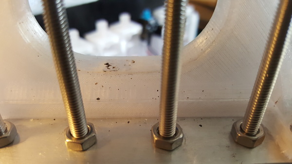
You can see in some of the slow-motion video that the bearing mostly rolls against the plastic rather than rubbing, which is handy.
Results
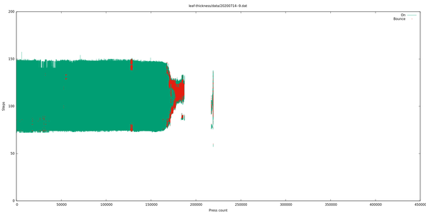
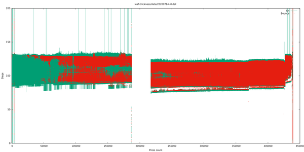
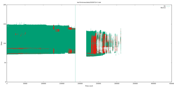
It is quite hard to quantify what is a failed switch and what is not, because sometimes there is a lot of contact bounce even in a perfectly good switch. For example, here's the chart from the commercial "control" switch:
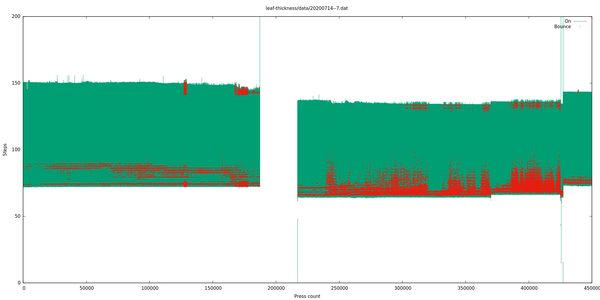
The gap between 180,000 and 210,000 is where the motor had stalled but the software didn't know (for this reason I subtracted 30,000 from the press count of every switch that exceeded 180,000). I expect it stalled because the broken leaf spring from one of the failed switches got wedged and made it harder for the platform to move up and down. Don't know.
The "step" around 425,000 is where I stopped the motor overnight and then started it again the next morning. There is a step because the 0 position at top-dead-centre was not quite identical.
But given that this switch still appears to work completely fine, we know that we can have at least this much bounciness (red) and not consider it a problem. For this reason I mostly ignored bounce information and classified a switch as "failed" only after it had either clearly stopped working entirely, or its activation range had become unpredictable or very small. Typically the switch gets bouncier over a long period but still works fine, and then its activation range degrades over quite a short period, and then the leaf spring breaks off and it either stops working entirely, or comes on and off unpredictably due to the machine vibration, if the leaf spring fell off in a way that can still short the contacts.
This is what I estimated to be the useful lifetimes of the switches, grouped by leaf spring thickness:
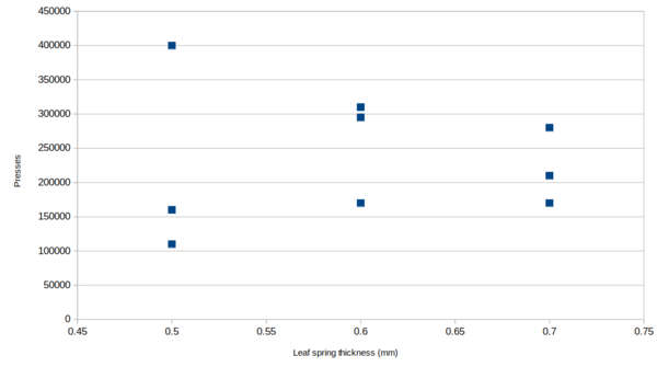
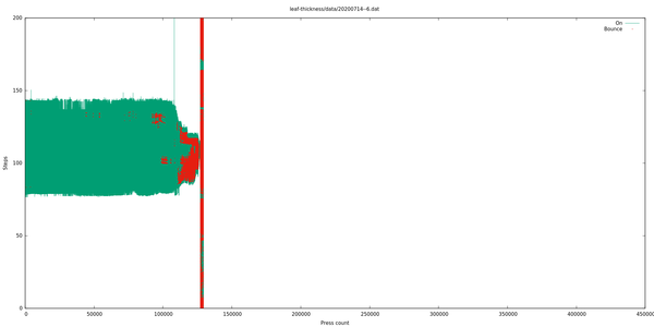
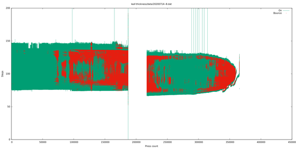
(The full charts of switch performance are available at the very bottom of this post).
So... I don't know what to make of this.
The (0.5, 400000) data point is from switch 0. If you look at the range of switch activation positions in the graphs at the bottom of this post, then you'll see that switch 0's was much smaller than the others for the entire test. This implies that the wire was not making contact for as long, which means there is less stress on the leaf spring. That is probably the reason that it lasted longer.
If we say switch 0 is an outlier and ignore it, then what remains could look something more like a bell curve with a peak around 0.6 mm. So I'll probably stick with 0.6 mm leaf springs.
If the reason that switch 0 lasted so much longer really is because its activation position was in the wrong place (presumably I bent the leaf spring during assembly), then we might find that the switches can be made to last longer if we deliberately move the activation position down, which is a compromise I experimented with on the copper-tape-based contacts, but not to great effect. I'm not yet sure whether I will try this out with the leaf spring contacts, or whether I just say "enough is enough" and move on to making the keyboard.
Keyboard design thoughts
I feel like this project is dragging on more than long enough, so I ought to try and get the keyboard finished before I lose interest and stop working on it, which is my usual modus operandi. To that end, I intend to proceed with roughly the existing switch design, even though it isn't good for quite as many presses as I'd prefer.
Key height
The only changes I definitely want to make to the switch design are to reduce the height. In order to produce a keyboard as slim as my Filco (which is about typical for off-the-shelf mechanical keyboards), I'd need to lose 18 mm of height, compared to my macro keypad. I have found 11 mm so far, as follows, which is probably close enough to be tolerable.
- 5 mm: put the Arduino on its side at the back of the board, instead of flat underneath it
- 2 mm: remove the rubber feet
- 1 mm: reduce the gap between the keycap and switch body at bottom of stroke
- 1 mm: reduce the height of the keycap
- 1 mm: reduce the thickness of the bottom of the switch body
- 1 mm: reduce the thickness of the attachment of the leaf spring to the plunger
Only 2 mm of this actually requires any changes to the switch design, and they seem relatively harmless, so I expect not to have any trouble, although I will do some testing to make sure it doesn't significantly affect the switch lifespan.
Copper wire
"m0xte" on HN said that the copper contacts will oxidise "almost instantly". This hasn't been an issue so far, so I'm not sure how "instantly" I should expect it. Nonetheless, I agree in principle, so I have purchased some gold-plated copper wire. It is sold for jewellery-making, and I previously experimented with some of Emma's sterling silver jewellery-making wire and found that it didn't conduct very well, I think it had a very thin layer of varnish on it. If the gold-plated wire I have bought has varnish on it then I probably won't bother trying to use it, but if it conducts easily then I will. It is 1 mm diameter gold-plated copper wire bought on eBay, I have ordered 4 metres at a cost of £1/metre which is probably not quite enough for the full keyboard, but enough to test with.
Case halves

SiCK-68 is a 3d-printable mechanical keyboard design using off-the-shelf switches. It looks cool, and although I can't use it with my switches, it is still good inspiration for case design.
This is how the SiCK-68 goes together:
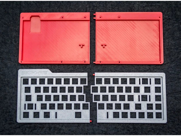
A full keyboard case will not fit on the bed of my printer in one go, which means it needs to be split into 2 halves. I was umming and ahhing about the best way to do this (I don't want the halves to be too floppy, I want a good rigid connection). I think I'll do it basically like the SiCK-68: holes in each half, with dowel pins to join them. If I make sure to use plenty of epoxy on the pins and along the split line, maybe it'll be strong enough. I'm probably not going to be hitting anything with the keyboard, so as long as it can stand up to furious typing, I expect it'll be fine.
Layout
As far as I've been able to determine, there isn't actually a standard key spacing. Figures I could find ranged from 18.8 mm up to 19.3 mm. I measured my Filco and found that they appear to be placed at 19.1 mm intervals. I'll probably use a round 19.0.
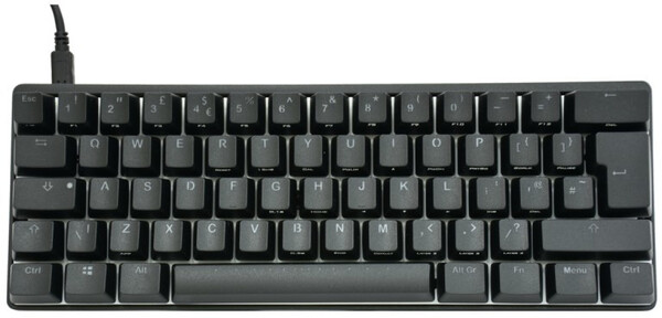
I intend to use an Arduino Pro Micro for the microcontroller. The Pro Micro has 16 available IO pins, which means the largest keyboard matrix we can use is 8x8 or 64 keys. This precludes using the Tenkeyless layout which I use at the moment, or even the TADA68 layout which the SiCK-68 uses, but does allow a 60% layout, like this:
You could certainly pick a microcontroller with more pins. Jamie recommended the Teensy 2.0, which is available on eBay for £9 and judging by the pictures has either 27 or 29 (I'm not sure about 2 of them) available IO pins, which provides for up to 182 or 210 keys, which should be Enough For AnyoneTM. Another possibility would be to use 2 microcontrollers and have them communicate internally to create a larger keyboard. It might even be funny to logically split the keyboard into 2 completely separate halves, each unaware of the other, and each controlled by a single Arduino. Linux would think you were using two keyboards but that's probably not a problem.
I already have a bag full of Arduino Pro Micros so I'll use one of those instead of buying a Teensy. And, besides, the fewer switches I have to wire up, the better.
I don't know if I will actually get on with a 60% layout. I've never used one before. In practice I never use the right Windows key, context menu key (???), or Ctrl key, so I'll probably use these as modifiers to make it possible to type keys like Home/End/Delete, backticks, arrow keys, and so on. I expect there is already some popular way to do this with QMK, I'll just need to research it a bit. There is actually both physical space and 8x8-matrix space spare for 5 keys in place of the 4 large keys to the right of the space bar, without even making the space bar shorter, so I could consider adding an extra modifier key there.
I'm basically settled on using QMK for the firmware. Writing my own keyboard firmware sounds like fun, but it's also the same kind of fun as designing my own switches, and I've probably had plenty of that kind of fun in this project already.
Keycaps
After I wrote last time about my troubles with the KeyV2 parametric keycap library, its creator Bob emailed me to explain how to use it! He even went as far as implementing a custom stem module which matches the design of my stems, so I am now definitely going to use KeyV2. This is a massive win compared to modelling every individual key in FreeCAD.
KeyV2 also has support for putting the legends on the sides of the keys, which I want to do because it gives superior print quality on the lettering, compared to printing them on top, and it looks cool.
That's all for now. The rest is just graphs from the switch test.
Test data
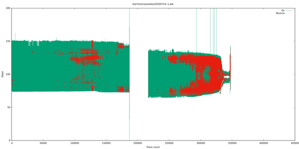
0. 0.5mm leaf spring
400,000 presses.
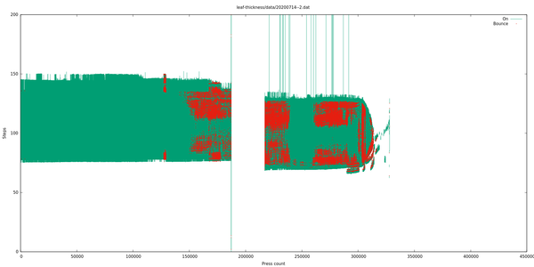
1. 0.6mm leaf spring
295,000 presses.
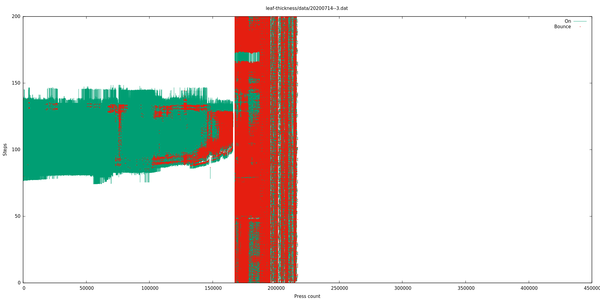
2. 0.7mm leaf spring
280,000 presses.
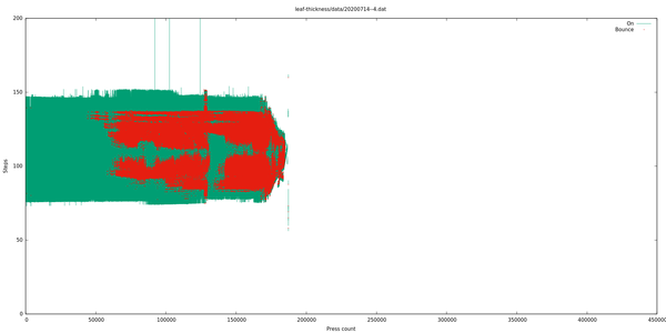
3. 0.5mm leaf spring
160,000 presses.
4. 0.6mm leaf spring
170,000 presses.
5. 0.7mm leaf spring
210,000 presses.
6. 0.5mm leaf spring
110,000 presses.
7. "kaiche" commercial switch
>450,000 presses, still not broken.
8. 0.6mm leaf spring
310,000 presses.
9. 0.7mm leaf spring
220,000 presses.