
Lichess has recently released a Boards API, allowing anybody to interface a physical chess board with lichess in order to play online games using an automatic board. I previously thought about implementing my Strange Chess Clock using an automatic board, but never got round to it. With lichess now supporting online play with an automatic board, it's hard to justify not making one!
Basic operation
There are only 2 things an automatic chess board really needs to do. It needs to be able to move the pieces on the board, and it needs to be able to detect where the player has moved the pieces on the board. You can view it as an input/output device: take input in the form of the player's moves, and provide output in the form of the opponent's moves.
Complications can arise in certain designs, because in addition to basic piece moves, you need to be able to input and output:
- knight moves: knights are able to jump over other pieces, you need to account for this
- captures: a piece gets removed from the board and the player's piece takes its place (in particular, if you only measure square occupancy, you might not know which piece was captured)
- castling: the rook needs to jump over/around the king
- pawn promotion: as input, you need to detect which type of piece the player promotes to; as output, you need to grab a captured piece and place it on the promotion square
Approaches
Mechanical Turk
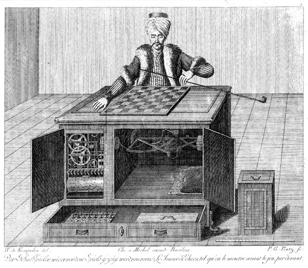
Hailing from 1770, the Mechanical Turk was the world's first automated chess-playing machine. It actually wasn't fully automated, there was just secretly a human inside who was providing the intelligence (an AI strategy that is still alive and well in Silicon Valley, I might add).
Each chess piece had a magnet in its base, and there was a corresponding magnet on a string underneath each square on the chess board. By observing which magnets were attracted upwards to the underside of the board, the operator could tell which squares had pieces on. The operator had a small pegboard chess board inside the box, on which he duplicated the game. Having decided on a move, he could move the Turk's arm using a pantograph-type linkage, and thereby move the pieces on the real board. This was accompanied by a fair amount of clanking and clockwork noises to make the illusion all the more convincing. I imagine it took quite some skill to operate the Turk's arm without knocking all of the pieces over.
Chess computers
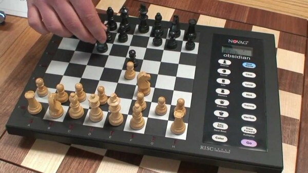
I have a chess computer (not pictured), it's quite a good way to play longer games at home. It's hard to find an opponent online to play a game that might last 4 hours, and even if you find one, it's easy for one side or the other to get distracted or lose interest. A chess computer is a good way to sit down at a real board and play a long game of chess without distractions.
Typically you input your moves by pressing down on the piece you want to move, then moving it, and then pressing down on the square you moved it to. There is a membrane switch underneath each square, which is what you're actuating by pressing the piece down. Once you've made a move, the computer thinks for a while and eventually beeps to alert you that it's decided on a move. The LCD display then tells you what it wants to move in a basic algebraic notation, e.g. mine says "E7E5" if it wants to move the piece from e7 to e5. You are then responsible for moving the computer's piece, the same way you moved your own: press down on the square you're moving it from, then press down on the square you're moving it to.
This is quite good, but we ought to be able to detect the user's move without making him press down on the squares, we ought to be able to apply the computer's move without making the user move the pieces, and it ought to be a bit hackable so that we can plug it into lichess for example instead of only being able to play against the built-in AI.
If you're not familiar with chess computers, you might enjoy IM John Bartholomew's video about his Excalibur Explorer Deluxe chess computer.
Light-up squares
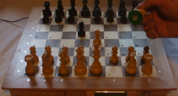
An improvement over the basic chess computer is to put a light under each square. Instead of indicating its move by saying "E7E5", the computer simply lights up the square it wants you to move a piece from, and then the square it wants you to move the piece to.
I've watched a demo of quite a good DIY implementation.
Stepper motors
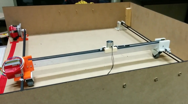
If we want the computer to physically move the pieces itself, the most obvious way is to use a magnet to grab the pieces, and use stepper motors to move the magnet. You need a horizontal and vertical axis, and then you need some way to grab the pieces from underneath using the magnet. One approach is to use an electromagnet which is switched on and off as required, and another approach is to use a permanent magnet that is raised up and down with a solenoid, servo, or something else.
Most of the problems with this approach stem from the fact that you can only move the pieces in 2 axes. If a knight needs to jump over some other pieces, you need to figure out a way to get it to its target square without moving it off the plane of the board. This normally means ensuring that the pieces are small enough to give sufficient space for the knight to move between the other pieces, but in some cases it means moving other pieces out of the way first, or moving the knight through a more complicated route.
Stepper motors also tend to be quite noisy, which can rather disrupt the ambience of a quiet game of chess.
There are quite a few DIY projects on YouTube that implement this sort of mechanism, of varying standard and completeness level. One of the better ones is Wireless Arduino Powered Chess because it moves the pieces quickly, quietly, and in sensible routes.
There was actually a commercial board available in 1982, from Milton Bradley, and it seems to work quite well in this video. At 1:45 you can see it perform a knight move by first moving the pawn out of the way of the knight's path.
Robotic arms
Instead of using stepper motors underneath the board, you can use a robotic arm above the board that physically grabs and moves the pieces. This has the advantage that you can jump the knight over the other pieces without issue, but comes with a risk of smacking the human if he doesn't get his hand out of the way fast enough, and also has potential reliability problems because making a robotic hand that can consistently grip a chess piece is quite hard.
There's quite a good Instructable by Nicholas Maselli called Homemade Chess Robot which uses a gripping hand:
One of the more polished DIY robotic arm projects is Raspberry Turk. Raspberry Turk solved the problem of the hand gripping the pieces by putting a small steel rod in the top of each piece and using an electromagnet on the arm to grab the steel rod.
Magnet sensors
In addition to moving the pieces, we also need the machine to detect which pieces the player has moved. An obvious way to do this is to put a magnet in each piece (which you potentially already have if you're moving the pieces with stepper motors), and a hall effect sensor or reed switch under each square. You know what move the player made because you know what square a piece went missing from, and you know what square a piece appeared in. Assuming no shenanigans on the part of the player (e.g. putting his pawn to one side and picking up a queen), you know that the square that gained a piece got the same piece that was previously on the square that lost a piece.
This gets more complicated when a capture is made. When a piece is captured, one square loses a piece, but no square gains a piece, and in some positions the piece that moved has more than one capture available, so the move is ambiguous. To get around this, you can continuously scan the hall effect sensors for the presence of a piece so that you can notice the brief blip when the captured piece disappears before the capturing piece replaces it. In the event that this is not detected, it will be up to the player to lift his piece up and put it back down to show which square it went to.
An alternative way to get around this problem would be to have (for example) North polarity at the bottom of the white pieces and South polarity at the bottom of the black pieces. You can then tell which capture was made by noticing which square got its polarity reversed. If moving the pieces from underneath with an electromagnet, you would also need to be able to reverse the current that is applied to the electromagnet, but this is doable.
NFC, RFID, etc.
To get an even better idea of which piece is on which square, you could equip each piece with a small NFC, RFID, or similar chip that identifies it. Then you need a sensor under each square which has enough range to communicate with a piece directly above it but not enough to communicate with pieces on adjacent squares.
DGT manufacture a ~$600 chess board which can detect which pieces are on which squares, and these boards are commonly used at high-level chess tournaments to provide real-time game data online. They look just like normal boards:
I initially assumed that the DGT boards used NFC or RFID, but this Chess Piece Identification Technology blog post includes this snippet from the now-defunct "chessprogramming.wikispaces.com":
The patent-registered DGT sensor technology recognizes pieces containing piece-type and piece-color specific passive LC circuits with a resonance frequency of 90 to 350 KHz, the coil on ferrite core. Squares and their respective pieces (if any) are scanned by 2 x 8 silver-ink printed trace loops on a polyester film placed under the board, file and rank sequentially selected by analogue switch multiplexers, feeding back the output signal of an amplifier via the selected inductive coupled LC circuit to its input, forcing oscillation in piece specific resonance. Measuring the signal frequency or its period via a digital input port by the controller firmware to convert it into appropriate piece codes takes about 3 ms per square.
Which is a really interesting way to do it, and makes complete sense given the limited number of piece types and colours that must be identified. It even seems like it should be possible to make a really thin (like, 3 sheets of paper) panel that can be placed underneath ordinary standard-sized chess boards to provide the same effect, and then it would "just" be a case of making compatible coils and sticking them in some chess pieces, and a controller that constantly scans the squares, and you've duplicated the DGT product for substantially cheaper. That might be a fun project on its own.
It's not obvious to me, from reading that quote, whether there are 2 frequencies that identify the colour and 8 that identify the type, and therefore each piece needs 2 coils, or whether there is 1 frequency that identifies a colour and type, and therefore each piece has only 1 coil. Seems like either way would work, and putting only 1 coil in each piece would be easier and cheaper. It does mean you need to scan each square for 16 different frequencies instead of only 10, but I can't see that being a problem.
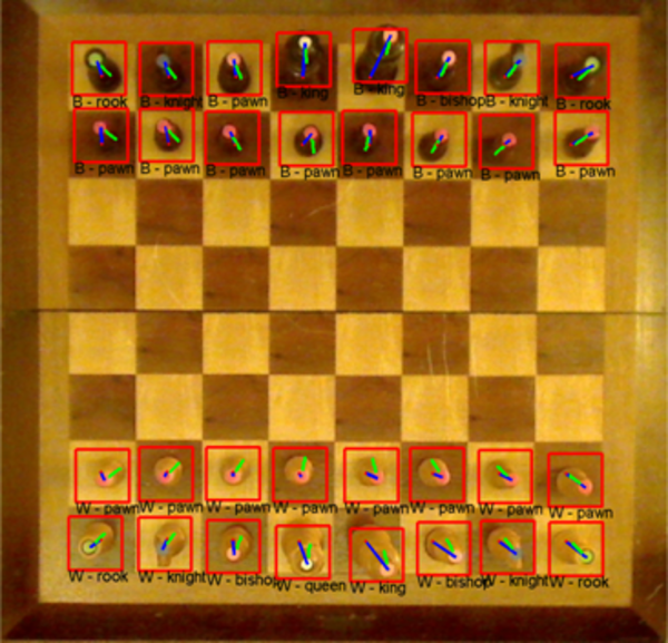
Computer vision
Computer Vision is relatively accessible these days, so just pointing a camera at the board and training a neural net on it is a perfectly viable solution. Raspberry Turk works this way (although the computer vision there is relatively minimal - most of the time it is only testing for which colour is on each square, and inferring what piece is there based on what it already knows about the position), and Daniel Bowers has a great blog post on Robot Arm, Chess Computer Vision.
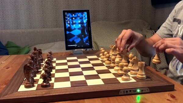
SquareOff
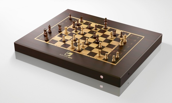
SquareOff is a commercial implementation of the stepper motor/magnet sensor solution. The base model costs $390 and it looks very promising, except it's not very hackable (e.g. you can't use it to play on lichess) and it requires the use of a proprietary smartphone app. Such a shame, because it seems to work well. If they'd let us control it with a USB serial port instead of a phone I'd have considered buying one.
Regium
Regium was a KickStarter project launched this year (and now suspended for being an obvious scam). It purported to use a high-density grid of tiny electromagnets underneath the board surface to move the pieces.
If it existed and worked, this could actually meet many of the claims made by the Regium KickStarter campaign: you could use the electromagnets to lock the pieces in position for transport, to move multiple pieces simultaneously, to move the pieces quickly and silently, etc. In fact, using stepper motors to move an electromagnet around is just a really low-fidelity way to manipulate the magnetic field underneath the board. Comparing it to visible light, if the stepper motors are waving around a light on a stick, the Regium board is an LCD panel.
Unfortunately, it doesn't exist and it doesn't work, and the product demo videos were faked. It is a great idea though and I'd be really interested to see if anybody could actually make it work.
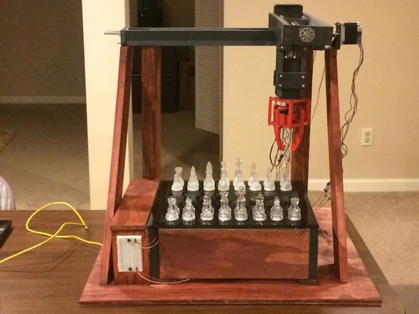
My design
I'm using stepper motors to move an electromagnet, with magnets on the bottoms of the pieces, and hall effect sensors under the squares to sense the pieces. I designed the mechanical parts in FreeCAD and put them together using the A2plus workbench.
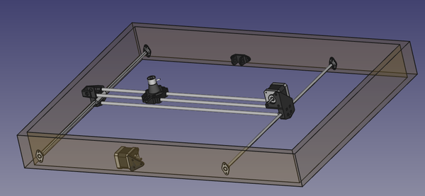
(The reason the case in the model is rectangular is because I was originally planning to have a control panel to one side of the board, but I'm now planning to have it as a separate unit on an umbilical cord so that it can be rotated to face either the black side or the white side of the board).
This was my first time using the A2plus workbench and initially I liked how easy it was to define constraints between the parts. Unfortunately I found that if I changed any of the parts in any way, then when I updated the part in the assembly, A2plus had lost track of which pieces of geometry were supposed to be constrained. This is very annoying and means you need to redefine the constraints for a part every time you change the part. I read somewhere that A2plus is best used when you have already committed to the design of the parts and you just want to assemble them together, but that is not really a useful workflow. If I've already committed to the design of the parts, I can just print them out and assemble them together in real life! The point of the assembly workbench is that I can design the parts around each other in an iterative way until I'm happy with how they fit together. So I'm on the lookout for a better assembly workbench. I've read that Assembly4 solves this particular problem because it defines the constraints between parts relative to their local coordinate systems instead of relative to particular pieces of geometry, although I couldn't quite understand the Assembly4 UI so I haven't got far enough to try it out yet.
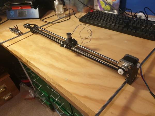
I 3D printed the parts in 3DXTech's CarbonX Nylon+CF, this is a nylon-based filament reinforced with carbon fibre to increase its stiffness. For these particular parts, ordinary PLA would have been more than sufficient, but it's always cool to use carbon fibre.
I'm planning to deal with knight moves by allowing enough space for the knight to move between pawns, and in the case of larger pieces in the way, by moving one of the other pieces out of the way first, like on the Milton Bradley board. I'm planning to handle castling and captures by allowing the stepper motors to access the centres of the squares of a "virtual" 10x10 board, providing access to 1 extra square along each edge of the board. The rook can move through this virtual square to pass to the other side of the king, and captured pieces can be placed on a virtual square. When the player promotes a pawn, I'll have the UI on the control panel ask what piece he promoted to, and when the opponent promotes a pawn, I'll have the UI on the control panel instruct the player to place the appropriate piece on the promotion square.
Electronics
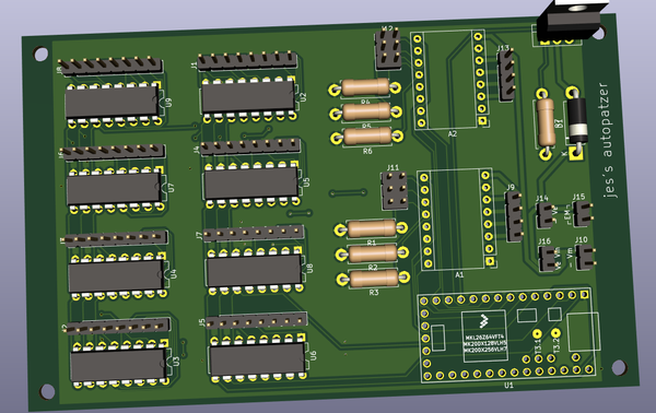
For the electronics, I'm using a Teensy 3.2 for the microcontroller. It's basically the same as an Arduino Nano except a bit smaller, with more pins available, more memory, and more CPU power. To drive the stepper motors I'm using 2x A4988 breakout boards salvaged from my old 3d printer, which is also where I got the stepper motors and the linear bearings from. I'm using analogue hall effect sensors instead of digital ones, just in case it ever becomes useful to detect a piece that isn't quite centred, for example. To read the signals from the 64 hall sensors I'm using 8x CD4051 8-to-1 analogue multiplexers. I'm using a cheap no-name eBay electromagnet to grab the pieces, and driving it using an IRF520 MOSFET.
I've included provision for a jumper to bridge the motor voltage and the electromagnet voltage together. I expect that both of these will run on 12v, but if I ever want to change the voltage of one of the parts, I can easily remove the jumper and supply a different voltage. I've also included provision for 3 jumpers next to each of the stepper drivers, this is so that I can change the microstepping mode. For maximum speed I expect I will be running with microstepping disabled, but it is possible that whatever speed I settle on will be attainable with some microstepping enabled, and that should quieten the motors down a bit.
I designed the PCB in KiCad, and PCBWay have generously agreed to manufacture it for me for free, so expect some commentary on the PCBWay board soon.
Mechanics
I mounted the mechanical parts inside a plywood frame, and made the top of the board out of 6mm MDF.
The top needs to be as thin as possible in order to help the electromagnet grab hold of the pieces. But I also don't want it to be too flexible. Several other projects I've seen have used a glass top because glass is thin and stiff, but it seems a bit fragile for my taste. I considered using a sheet of some sort of plastic, but MDF is more convenient. Normally I prefer making things out of plywood than MDF because it is stronger and MDF doesn't hold screw threads very well, but I have found plywood at this sort of thickness to be quite poor quality, and since I don't need the top to hold any screw threads anyway, MDF will suffice.
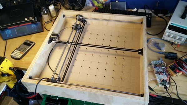
(The board is upside down in that photograph. The intersections of the grid are the centre points of the squares on the virtual 10x10 board, and you can see there is a hall effect sensor superglued under the centres of the central 8x8 squares).
The linear bearings are a little bit on the... crunchy side. I have certainly lost at least one of the tiny ball bearings from inside while fitting the rods, and it's possible a few others have escaped without me noticing. On a few occasions I have observed the bearings bind up while trying to move them quickly, so I might have to replace them at some point.
If you've worked with stepper motors before you might notice a glaring omission in my design: there are no limit switches! That means when the machine wakes up from a cold boot, it has no idea what position the electromagnet is at relative to the chess board. I watched a video How Old School Floppy Drives Worked by The 8-Bit Guy a while ago, and learnt that some older floppy drives homed their stepper motors by simply driving them to one end of the axis for long enough that it has definitely reached the end. The head will crash into the end at some point and stop moving, resulting in an unnerving grinding noise as the motor tries to drive it further. But this does no harm to the stepper motor, and as long as the mechanical assembly is strong enough to handle it, no harm is done at all. I thought this was a very funny solution so I intend to use it in the chess board. In the absence of a proper name, I think I'll refer to it as "crash homing". In the case of my chess board, it might also be possible to detect the position of the electromagnet by switching it on and wiggling it around and trying to find it using the hall effect sensors, so maybe that could be the primary method, and crash homing is just a last resort.
Software
I initially wanted to use the AccelStepper library to control the stepper motors. It allows you to specify a maximum acceleration and maximum velocity for your motors, and then move them to target positions within these constraints. It also includes a "MultiStepper" class that can control more than one stepper motor at a time in order to move in a straight line to a new target position. Unfortunately, the MultiStepper class does not implement acceleration, so you have to decide whether you want to control the axes independently, but with acceleration, or whether you want to coordinate the 2 axes, but only move at a constant speed. I want to coordinate my 2 axes and move them both with smooth acceleration, so I think I'm going to have to implement that myself.
Many of the stepper motor chess boards seem to do a very poor job of routing the pieces along the board surface, which makes them move very strangely. For example, in one project I observed a bishop move in a path like this:
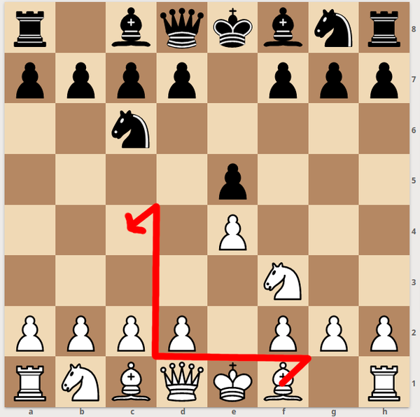
It is obvious why this has happened: the machine is programmed to first move the piece to the corner of its square (with big enough squares, moving along the edges of squares ensures you can never crash into other pieces), then move in the horizontal direction, then the vertical direction, and then finally move to the centre of the square. This is surprisingly common in many of the YouTube demonstrations, so part of me wonders if they're all university coursework for the same course, and the professor has advised that they implement movement this way. But in my opinion this can be improved so that the pieces move more naturally without too much programming difficulty, so I intend to do so.
So far I've got as far as moving a single bishop back and forth on top of the board, and you can see a demonstration of that if you want.
Trouble with magnets
I already had a magnetic chess board, so I was hoping to be able to use the pieces from that set on the automatic board. It turns out that the magnets in those pieces are much too weak. I have removed all of the original magnets and replaced them with neodymium equivalents, and the electromagnet is now able to grab hold of the pieces and slide them around the surface of the board.
Unfortunately, when pieces get too close together, they repel each other because of the strength of the magnets in their bases. It would work fine for most pieces because they don't need to get close to each other, but when the knight tries to move between 2 other pieces, it pushes each one away. I really need to find a magnet solution that is strong enough for the electromagnet to grab it, but weak enough not to repel adjacent pieces. If you have any thoughts on this I'm interested in hearing them. In case it helps: I have 48mm squares, which means when the knight moves between two pieces the centres of the magnets will be 24mm apart. I have 12mm holes in the base of most pieces and 10mm in the pawns, and I have 4mm depth available. There is 11mm between the top of the electromagnet and the bottom of the chess piece, 6mm of which is the MDF board, and 5mm is clearance for the hall effect sensors although this could probably be reduced slightly once I've wired it all up.