
My automatic chess board (the "Autopatzer") has reached the point where last night I was able to play its first online game against a real person using lichess's Boards API.
Feroz described playing online chess over a physical board as "very lockdown chic", which I liked.
And, since a lot of people ask:
patzer, n. A poor or amateurish chess player.
Overview
To actuate output moves, the board has X and Y axis motion stages, driven by NEMA17 stepper motors with GT2 timing belts, with an electromagnet mounted on the carriage. It's basically like a 3d printer but with no Z axis, and with an electromagnet instead of a hot-end. To detect input moves, the board has a hall-effect sensor underneath each square.
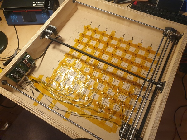
The electronics are controlled by a Teensy 3.2, which speaks to a Raspberry Pi over USB serial. All of the source code (and CAD models, and PCB design) are in the jes/autopatzer github repo.
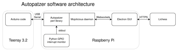
Miles is currently furloughed from his day job and was looking for a project to do, so he has been working on the Electron app that provides the GUI displayed on the touchscreen.
You could argue that the board-related logic could have been written in Javascript and then it could be in the same program as the Electron GUI. You'd be right. I just found it more convenient to do the board logic in Perl.
The Raspberry Pi is mounted in a 3d-printed case at the side of the board and has a 5-inch 800x480 HDMI touchscreen:
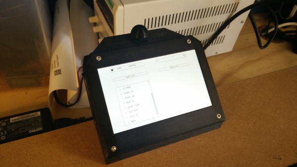
The touchscreen is there to allow seeking a game, offering/accepting a draw, and resignation, and displaying clocks, move history, and current input move. There is a Cherry MX blue keyswitch mounted on the plastic case which provides basically the function of a "clock button": having moved a piece, the user must hit the button to confirm the move and end the turn. Hitting the button triggers an interrupt on one of the GPIO pins (which I initially tried to detect in Perl, but RPi::Pin was causing segfaults, hence the Python program).
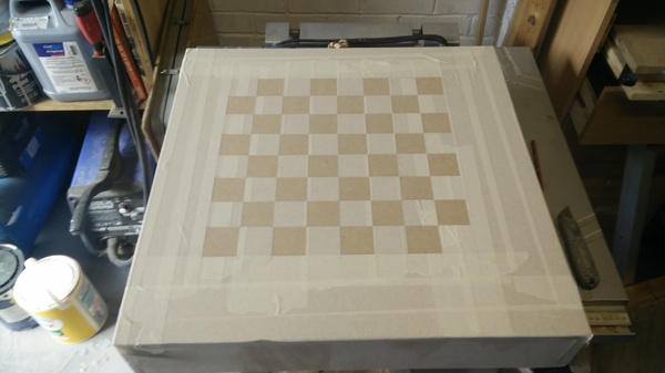
Painting the squares
I first covered the board surface in masking tape.
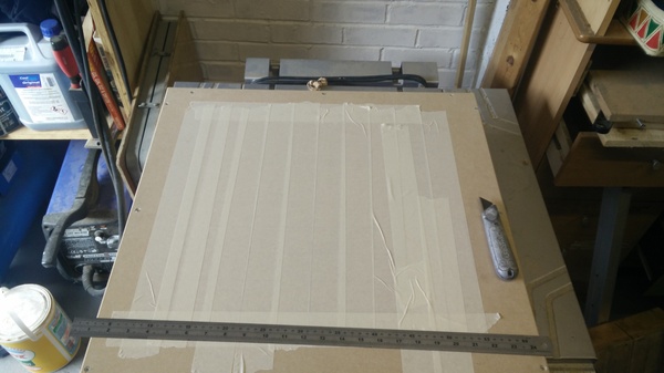
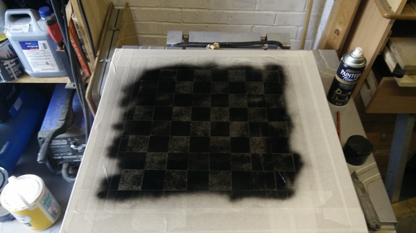
Then marked out the grid and cut every other square out.
Then spray-painted the whole thing black.
Then peeled off the rest of the masking tape.
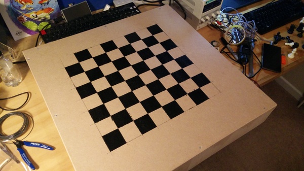
I don't think this worked spectacularly well, quite a lot of paint seems to have seeped under the tape and messed up adjacent squares. It's adequate though. After this, I sprayed several coats of lacquer over the top of the board to make it look nicer, and to reduce friction for moving the pieces.
Electronics
Inside the board
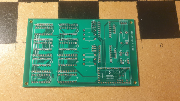
PCBWay generously supplied me with free PCBs for this project (I only needed 1, but their minimum order is 5). The PCBs are excellent quality as expected, not obviously any different to ones I've ordered from JLCPCB in the past. I did have to pay an unexpected fee of £18 to DHL before I could receive them. It's not entirely obvious what this fee was for, I don't think it was import duty. DHL called it an "advanced payment".
And here it is installed:
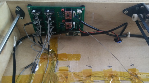
I realised after I started putting it all together that I had failed to include any pads on the PCB for power to the hall-effect sensors. I solved this by supergluing a 2-pin right-angle header to the board and running wires to where I needed them. It's hidden by the lower stepper motor cable in the photo so you'll just have to imagine.
The 2 red circuit boards are A4988 stepper motor drivers. I'm considering replacing these with some Trinamic drivers for "silent" stepper operation, if I can find some drop-in replacements that are cheap and pin-compatible. The red jumpers next to the red PCBs are selecting the microstepping mode. I originally thought I would not use any microstepping but ended up adding what I think is 1/2 microstepping, so I'm glad I bothered to add the jumper pins. The green jumper towards the bottom right is joining together the positive voltage for the stepper motors and the electromagnet. I have the capability to run them at different voltages (by removing the green jumper and adding a different supply voltage) but for now they're both running at 19v from an old laptop power supply.
The left half of the PCB has 8 headers for hall-effect sensor signals, and 8 corresponding CD4051 8-to-1 analogue multiplexers. The Teensy does not have 64 analogue inputs, so in order to read from 64 analogue signals, I use 8 multiplexers each with 8 signals. This takes up 3 digital outputs (used to select which channel to read, which is wired the same to each multiplexer), and 8 digital inputs (carrying the currently-selected signals from the multiplexers). The hall-effect sensors plugs are all labelled so that if I ever unplug them I have half a chance of getting them all back in the right order.
The grey wire running off towards the bottom-right of the picture is going to the electromagnet. I am slightly concerned that it is too thin for the amount of current it carries, but since it is only on for a few seconds at a time I don't think it will be a problem. I actually put a failsafe in the Arduino code to switch the electromagnet off after 20 seconds of inactivity to prevent accidental damage. It would still be possible to damage it deliberately, for example by sending a command to switch the electromagnet on every 20 seconds. But if you're going to do that you can just set the whole thing on fire with a blowtorch anyway.
Raspberry Pi
Here's the CAD model of the case around the Raspberry Pi:
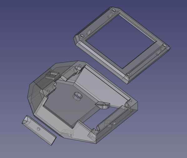
The rectangular piece at the left is a cover for the Pi's IO ports. It has a hole for a small magnet to hold it against the casing of the USB ports.
The HDMI touchscreen is held inside the top piece of the case with 4 3d-printed hold-down clamps, and the Pi is held to the touchscreen with a combination of the HDMI connector and (not pictured) the GPIO header plug on the back of the touchscreen:
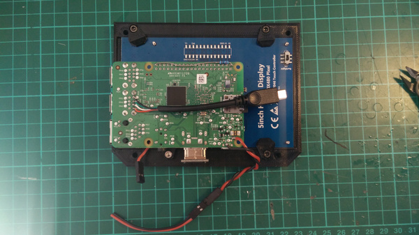
In that picture we also see a pull-up resistor for the keyswitch, between one of the GPIO pins and +5v, and a 2-pin header with 1 pin to ground and 1 pin to a GPIO pin, for the keyswitch (visible at bottom left of the Pi; it's plugged into the GPIO header on the top side of the board). There's also a MicroUSB cable soldered on to the pins for one of the USB ports, this is for speaking USB serial to the Teensy, and is done that way because there's not enough room for a proper MicroUSB plug. Similarly, power input to the Pi is provided by wires soldered to the board at the bottom. The USB port used for the connection to the Teensy is of course no longer usable as an actual port, so I have put a small 3d printed bung in it to prevent any trouble.
There are corresponding ends for each of these connections inside the other half of the case:
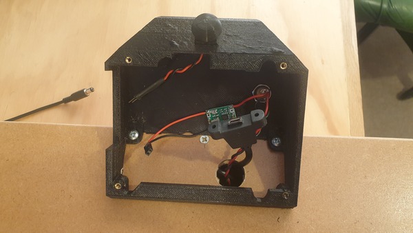
Not the best quality 3d printing but it'll do. The green PCB here is a buck converter to convert 19v from the power supply down to 5v for the Pi.
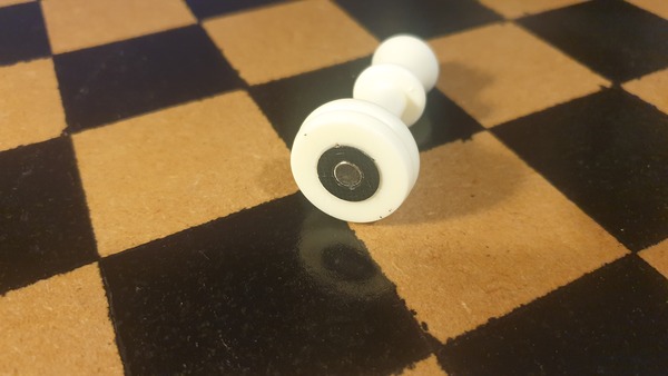
Magnets
Selecting magnets is one of the trickiest parts of the whole project. You need to put a magnet in the base of each piece, and the magnets need to be weak enough that 2 pieces can pass by each other without repelling, and strong enough that they can be grabbed by the electromagnet and sensed by the sensors. Tying into this is the mass of your lightest and heaviest piece (because light pieces are more easily repelled, and heavy pieces are harder for the electromagnet to move), the size of the squares (because that sets the distance between the pieces), the thickness of your board (because a thicker board puts the sensor further away from the piece), and the properties of the electromagnet.
I ended up with:
- cylindrical neodymium magnets, 6mm diameter, 6mm height, "N50" strength
- 48mm squares
- SS49E analogue hall-effect sensors
- 6mm MDF board (so the top of the hall sensor is 6mm away from the bottom of the magnet)
- Arbitrary no-name electromagnet, with the top of the electromagnet about 3mm from the bottom of the board (so 9mm from the bottom of the piece)
I would not necessarily recommend using analogue hall-effect sensors. I thought this would be a good idea because it would allow me to tune the signal threshold to adjust the sensitivity, but it just means it's tricky to pick a threshold value that works well with unstable power supply voltage. I think digital hall-effect sensors would work better. If you used reed switches instead you would be able to wire them up like a keyboard matrix and reduce both the amount of wiring and the number of IO pins required. I don't know how sensitive reed switches are, and they strike me as unreliable, so I did not try it, but it might be a better way.
I took my pieces from a magnetic chess set that I already owned, but the original magnets were too weak. I removed the original magnets, but the holes were too large for my 6mm magnets, so I 3d printed some sleeves which push-fit into the bottom of the piece, and then the 6mm magnets push-fit into the sleeves:
Still to do
We still have a lot of work to do to get the GUI prettier and more feature-complete. I need to get the Pi to boot all the way to the full-screen GUI without any user interaction required. I'd like to add some guards to the inside of the board to prevent the motors from being catastrophically driven into the PCB in the event that the homing doesn't work properly. I'd like to add limit switches instead of "crash-homing", because while crash-homing is a funny idea, and works OK for a floppy drive, it is slightly too violent to be acceptable in a device of this size. The perl library doesn't yet understand en passant inputs. The stepper motors whine slightly at idle even if they're not moving. Not sure why. I get an intermittent under-voltage warning on the Pi after it has warmed up a bit. I'm not sure if I need to adjust the voltage on the buck converter, or just add a capacitor across its output, perhaps both.
If you want to help with any of this, or build your own board, please get in touch: james@incoherency.co.uk, I'd love to hear from you. If others want to build one of these, then I'd be interested in producing an open-source design with decent CAD models and repeatable build instructions. Everything is in the github repo already, but it's not exactly easy to work with if you don't already know how.