I built a hacky USB interface to the Psion Organiser II that lets you send messages to it over USB serial via an Arduino Nano. It involves the organiser executing machine code stored in a string in its BASIC-like language, and it totally abuses the CPU's bus design. But it's simple and it works.
The motivation is that Martin wanted to use the Psion to display notifications, but couldn't find anywhere to buy the "CommsLink" module that connects it to a PC. I thought it sounded like a fun Arduino project, so I did it.
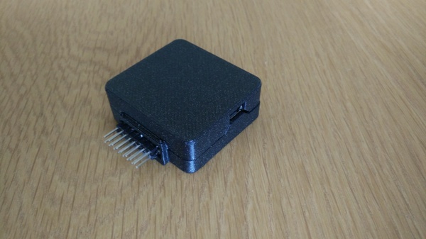
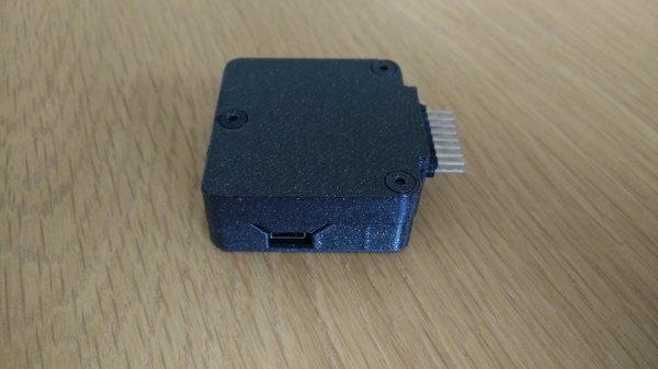
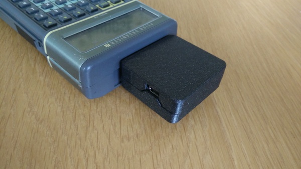
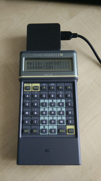
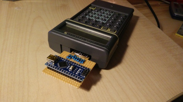
This is what the Psion looks like, with my homemade comms module plugged in:
My code and 3d printing files are all available on github.
If you are working with one of these devices then you should see Jaap's Psion II Page. It has lots of good information and documentation.
Hardware
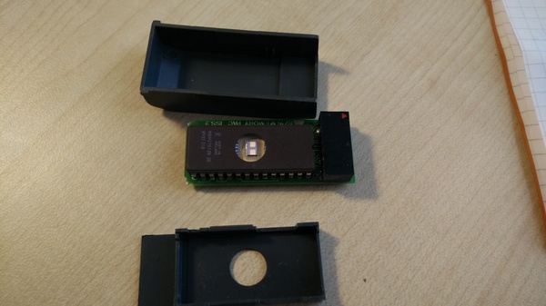
The Psion actually has 3 slots that peripherals can be plugged into. The first 2 are on the bottom of the device and are used to insert "datapaks". These are UV-erasable EPROMs which can be used to store code and data. The Psion has a weirdo "write-only" filesystem built on top of these EPROMs, which (I assume) "deletes" files by writing a bit to say that the file is no longer there, but can not reclaim used space. The only way to reclaim the space is to expose the little die window to UV light and erase the entire thing:
The third slot, the "top slot", is the one we're going to be using. It has 16 pins. The important pins are D0..D7 which are connected directly to the CPU's "port 2" data bus. There's also ground, +5v, and various other signals which we can ignore. Jaap has a page on top slot technical data
My first thought for the easiest way to write bytes from the Arduino into a program running on the Psion is to just assert the byte onto the port 2 bus and leave it there permanently. Then the program on the Psion can sample the bus at its own convenience. When we have another byte to send, we assert that byte instead, and the Psion will know it's a new byte because the value has changed. If we need to be able to write duplicate bytes then we can stick a 0x00 in between.
Unfortunately, this isn't quite enough, because it prevents the datapaks from working. All 3 slots are connected to the same bus of the CPU, but with 1 pin that tells you whether that slot is selected (CS1, CS2, CS3). Most of the pins are identical between all 3 slots. If you try to assert something onto the bus while some other peripheral is trying to use it, then you get bus contention, which means in the best case the computer doesn't work properly, and in the worst case is permanently damaged.
So what do we do about this? The ideal solution is to put some glue logic between the Arduino and the organiser that tests the CS3 pin (and "output enable" preferably) and only tries to assert anything to the bus when the top slot is selected, and the CPU is trying to read from the bus rather than write to it. (It's not sound to do this logic in software on the Arduino because even at 16x the clock speed of the Psion, the Arduino is not fast enough).
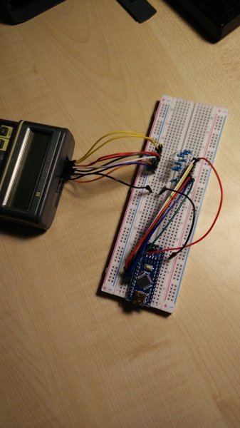
But since we know that the only other devices connected to the bus are the datapaks and the CPU, and we know that those things all respect the control signals properly, and we only need unidirectional communication, we can take a bit of a shortcut. I connected some digital outputs of the Arduino to the data pins via 510 ohm resistors (chosen mostly at random). This is low enough resistance to overcome the internal pullups on the data lines, but high enough that it doesn't interfere when the datapaks or CPU are trying to write to the bus. It's a really simple solution and seems to work well. So that's the hardware problem solved, the rest is just software.
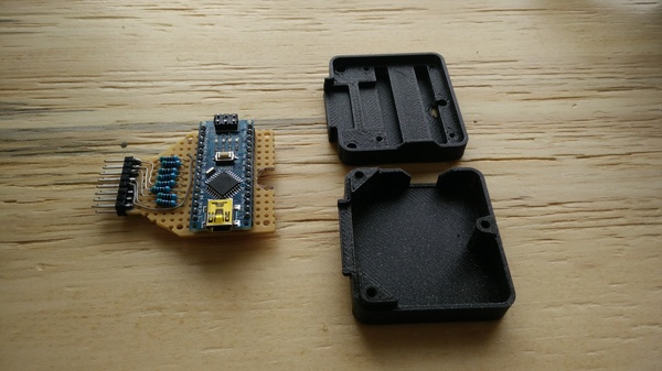
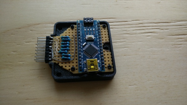
I initially got this to work on a breadboard, but built it up on a stripboard once I knew it worked:
Connecting a 2-row pin header to a stripboard is not easy because there is no sensible way to connect to both rows. I solved this by soldering the connector on one side and supergluing it on the other:
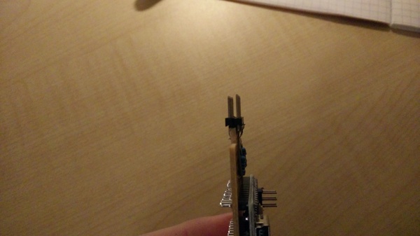
(And, actually, I didn't even have a 2-row header on hand, so I made this one by gluing two single-row headers together).
Software
We need to be able to read from port 2 and write to the display. The Psion has a programming language called "OPL". It's more or less the same as BASIC. Writing to the display is easy, because we can just use PRINT and have OPL sort it out for us. Reading from port 2 is more tricky.
Jaap's page on The System Variables is very helpful. We learn that port 2 is accessed at memory address 0x0003, and the direction (read or write) of the pins is controlled at address 0x0001:
Port 2 data direction register. Bit 0 controls the direction of bit 0 of [port 2] (1=output,0=input) and bit 1 control the direction of bits 1-7 of [port 2].
So we need to write zeroes into address 0x0001, and then read bits from the data pins in the top slot by reading address 0x0003.
It turns out we also need to tell the organiser that we want to use the top slot rather than one of the other slots. I'm not sure if one of the datapaks is left active if you don't do this, but I couldn't get it to work without asking for the top slot to be active.
We control which slots are active by writing to port 6. See Jaap's page for more info.
OPL has a POKEB command which can be used to write bytes into arbitrary addresses, and it has a PEEKB() function which can be used to read from arbitrary addresses. Great success, right? We just poke and peek and we can read from the top slot.
Not so fast! Just to make life more interesting, OPL deliberately blocks any attempt to read or write an address below 0x0040. This is very frustrating. It's probably done to "prevent you from breaking your device", but a.) if you're writing values into random memory addresses you should already have some idea of the risk, and b.) you can still break your device anyway with the workaround.
The workaround is to write some assembly language code to do your memory accesses, assemble it by hand, write the bytes into a string, and then execute the string from OPL as if calling a native machine code routine (which you are). Easy enough, but it's annoying that it's necessary. It wouldn't have been any trouble for them just not to block access from OPL! (In fact, come to think of it, maybe the easiest way to circumvent it is actually to work out where in memory POKEB and PEEKB() are implemented, and NOP out the test...)
I was very excited when I managed to use some machine code to read data from the top slot, then get those bytes back to OPL, print them to the screen, and observe that they changed when I pulled one of the pins on the bus high:
And then even better when I first got the complete pipeline working, getting text typed on Linux displayed on the Psion:
I eventually reached the following machine code routine to set port 2 to what I want, read a byte from it, stick the byte in the X register, and return (in my made-up assembly language dialect):
72 18 16  oim $18, $16 # allow writing to bits 0x10,0x08 in port 6
71 18 17  aim $18, $17 # enable the top slot and disable the other 2 slots
71 00 01  aim 0, $01 # input mode on port 2
96 03     ld a, ($03) # read from port 2 into A
c6 00     ld b, 0
36        push a
37        push b
38        pull x # make a 16-bit value out of a 0 and the byte we read
39        rts
I wrote this by consulting Jaap's HD6303 instruction set documentation.
I have never programmed a HD6303 before, so some of this is probably stupid (like spending 4 instructions to extend a byte in A to 2 bytes in X), but it does the job. With machine code in hand, we just have to write an OPL program to execute it.
I ended up with this:
DISPLAY:
LOCAL S$(17),A%,B%,C%
POKEB $7C,0
S$=CHR$($72)+CHR$($18)+CHR$($16)+CHR$($71)+CHR$($18)+CHR$($17)+CHR$($71)
S$=S$+CHR$(0)+CHR$(1)+CHR$($96)+CHR$(3)+CHR$($C6)+CHR$(0)+CHR$($36)
S$=S$+CHR$($37)+CHR$($38)+CHR$($39)
WHILE KEY<>0:ENDWH
WHILE KEY=0
A%=USR(ADDR(S$)+1,0)
IF A%<>B%
C%=USR(ADDR(S$)+1,0)
IF A%=C%
IF A%<>0
PRINT CHR$(A%);
ENDIF
B%=A%
ENDIF
ENDIF
ENDWH
The local variable S$ holds our machine code. Strings in OPL have 1 byte saying how long they are, followed by the contents of the string. ADDR(x) gives us the address of a variable, and USR(addr, arg) executes some machine code. So we can execute our code by calling USR(ADDR(S$)+1,0). I didn't figure this out on my own, I got it from Jaap's machine code tutorial.
The initial POKEB $7C,0 asks the Psion not to switch off the screen after a period of inactivity. The main loop is inside WHILE KEY=0 so that you can exit it by pressing any key.
The main loop reads a byte from the top slot. If the value is different to the last known value, then it reads again. If this second read is different, then it ignores them both. This is so that we don't get corrupted reads while the Arduino program is halfway through updating the values on the bus.
Having determined that 2 consecutive reads got the same value, we print the byte to the screen unless it's 0 (which is used to delimit consecutive outputs), then we update the last known byte to whatever we just read and loop again.
Although the current implementation is only unidirectional, it is probably possible to invent a protocol by which the "writer" can signal to the "reader" that it wants to swap roles, and then both sides invert their bus direction. I'm not sure if we'll need to do this, but hopefully it would only require a software change.
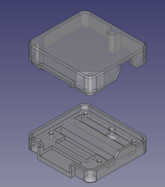
3D Printing
The last thing to do is make a nice plastic enclosure for the electronics. I recently fitted a 0.6 mm nozzle to my Prusa Mini (previously I was using the standard 0.4 mm nozzle). I think this is a great upgrade. You can print parts a lot faster, they're (supposedly) a bit stronger, and the nozzle doesn't clog as easily because larger impurities can pass straight through. The loss of detail is minimal, and only exists in the X/Y plane because you can still print with the same layer heights if you want. I think 0.6 mm should be the default!
I really like countersunk allen screws, I think they give a nice finish sitting flush with the surface of the part.