
I reached another good milestone on SCAMP this week: the physical hardware booted all the way up to the shell. Granted, it only happened once, and I couldn't type any input once it got there. But it suggests that there are no fundamental problems with the hardware design that will prevent the computer from working, which I am very happy about.
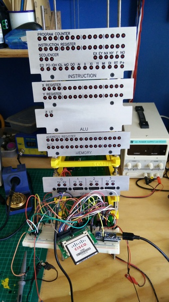
I'm currently "interacting" with the computer using an FTDI cable (basically a USB serial port). I'm still planning to eventually acquire some sort of hardware terminal, either a ready-made product or something I'll put together based around Marco Maccaferri's RC2014 VGA Serial Terminal Kit, which I use and like on my RC2014.
SCAMP boot process
The SCAMP boot process has 3 stages. There's the boot ROM, the kernel, and init. The boot ROM loads the kernel off the disk, the kernel stays in memory to provide system call implementations and loads init, and init (currently) just prints the message of the day and executes the shell, at which point the user is in control.
As measured in the emulator, it takes about 36 million clock cycles to go from zero to the shell, but this can be improved a lot. 60% of the time is spent reading/writing the disk. These functions are prime candidates for optimisation in assembly language. Also, init shells out to cat to print the message of the day, which is really an unacceptable performance cost at slower clock speeds. It would be better to have init read /etc/motd itself.
Boot ROM
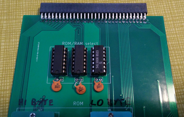
The boot ROM is stored on 2 EEPROMs (all SCAMP memory is based on 16-bit words, so there's one EEPROM for the least-significant byte, and one for the most-significant byte) which are permanently mapped at addresses 0 to 255.
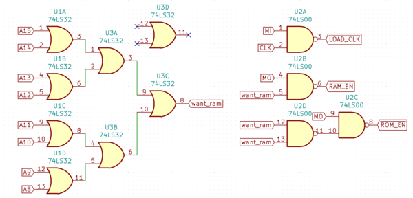
The memory card decides whether any given memory access should go to ROM or RAM based on checking the 8 most-significant bits: if any are 1 then it's RAM, otherwise it's ROM. This is accomplished with a pair of 74LS32 OR chips, and a 74LS00 NAND chip:
The first three 16-bit words from the disk are:
- magic number to verify that the disk contains a SCAMP kernel (0x5343)
- start address of kernel in memory
- length of kernel
The boot ROM loads the first 3 values, checks that they look sensible, and then continues reading the requisite number of words until the entire kernel is loaded into memory at the requisite address, and finally jumps to that address to start executing the kernel.
Currently every single one of the 256 available words in ROM are used, and the diagnostic messages are still a bit terser than I would prefer, but it fits, which is all that matters.
Kernel
The kernel has very little to do at boot time. It initialises the serial device (which is probably unnecessary since the boot ROM already did that), finds an unused block on the filesystem (for boring reasons), and executes /bin/init.
init
init has even less to do than the kernel:
system(["/bin/cat", "/etc/motd"]);
chdir("/home");
while (1)
    system(["/bin/sh"]);
But it takes a long time because system() in SCAMP/os is basically a practical joke taken too far: it swaps the running process out to disk, loads the child process, runs it, and then swaps the parent process back in and resumes where it left off.
CompactFlash interface
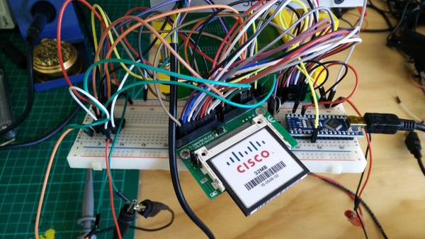
I chose to use CompactFlash instead of an SD card because the parallel access is much more convenient and performant than SPI. I'm using the CompactFlash card in "True IDE" mode, which also leaves the door open for potentially replacing it with a real hard disk at some point with minimal software changes. Happily, True IDE mode supports 16-bit transfers natively, so I don't even have to worry about combining 2 bytes into a word or splitting a word into 2 bytes. Unhappily, it seems to be little-endian, so the filesystem is kind of interlaced when viewed bytewise. It's tempting to swap the upper and lower byte by plugging them into the bus "backwards", but I think this might just create more confusion than it solves.
I bought a CompactFlash breakout board on eBay to get this working on a breadboard, and I may even use the breakout board on the final PCB because it seems a lot more convenient than soldering the CompactFlash connector myself.
I learnt how to speak to the card by reading a couple of PDFs that I found online:
- CompactFlash Memory Card Interface to the TMS320VC54x from Texas Instruments
- SanDisk CompactFlash Memory Card OEM Product Manual from SanDisk
But the set of information that you need to know is much smaller than either of those PDFs, so I intend to write some more beginner-focused documentation.
Graham told me that if your computer has a long bus (like mine does, and like the RC2014 does), then you may find that newer CompactFlash cards don't quite work correctly. I found that mine would sometimes drop certain values. Usually the same ones, but not in any pattern that was obvious to me. There are some details of the problem in PickledDog's rc-cfcard README:
the fast level transitions of modern CompactFlash are only intended for the short traces between card and interface in a system, and do not play nice with the long paths of the unterminated RC2014 bus
I'm not a high enough wizard to know what this actually means, or why it causes the behaviour I observed. But I took a punt on a much older CompactFlash card (you can identify the older ones by their lower storage capacity), and that one worked straight away, so there might be something in it.
Connecting the CompactFlash card to the SCAMP bus is mostly just a case of connecting up the wires in the right order, but a small amount of glue logic is required:
- IORD- = !DO
- IOWR- = !WR
- CS0- = A3 nand A8
DO goes high when the CPU wants a peripheral to output something, but the CompactFlash card wants an active-low signal, so we just invert it.
WR is generated by the UART card, based on DI (CPU wants a peripheral to input something) and the clock signal. We take this signal from the UART card and invert it for the CompactFlash card.
CS0- needs to go low when we want to select the CompactFlash card. I have dedicated the A8 bit of the address register to selecting CompactFlash, and conditional on A8, A3 selects the first card. (I'm not sure if there will ever be more than 1, but it doesn't hurt anything to provide for more now).
I was initially implementing this logic on the Arduino Uno that also generates the clock signal, and at this point the system booted up, which I liked. It took about half an hour to completely boot though, because the clock signal was only about 20 kHz.
Obviously I need to move the glue logic out of the Arduino and onto physical chips in order to make the real CompactFlash interface. All 3 of those operations can be provided by a single 74xx00 NAND chip, so that's what I tried.
Unfortunately it didn't work. I think the problem is that CompactFlash is based on CMOS logic, which is quite strict about having a good 5v for a logic 1, whereas TTL is allowed to output anything above 2.7v for a logic 1. I tried a 74LS00 and 74HCT00 but it didn't work with either of them. I have ordered a 74HC00, but I think this might have the same problem from the opposite direction: it will generate nice clean CMOS outputs, but will also require nice clean CMOS inputs. So if that doesn't work then I may try to generate these signals using bare transistors, and if even that doesn't work then I'll need to go away and learn harder.
Next steps
After I've got the CompactFlash card working with the glue logic in hardware instead of Arduino code, I will need to debug why input wasn't working when I got to the shell. I think it is supposed to work, and it works in the emulator which very-slightly emulates the physical UART, so I'm not sure what I missed. Hopefully it shouldn't be difficult.
Once the CompactFlash card and keyboard input are working, we're pretty much home free, because that's where the dark magic ends. The rest is just building the wooden case that I keep getting distracted from, connecting up the real power supply, making a real clock source, and fleshing out the system software and libraries in preparation for Advent of Code.