
I need to affix a rotary encoder to my oscillating steam engine to measure the crank rotation, so that I can plot pressure-volume diagrams from the real engine to compare to the simulation. Rather than buy a rotary encoder, I decided to make a light gate and slotted disc myself. I haven't done the slotted disc yet, but it will be a pretty trivial 3d print.
I made the light gate using components I already had in the junk box, and it only took a few hours, most of which I spent on trying to get the wrong kind of infrared sensor to work.
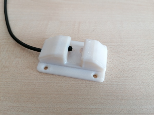
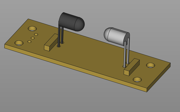
(The dark one is the photodiode, the clear one is the LED)
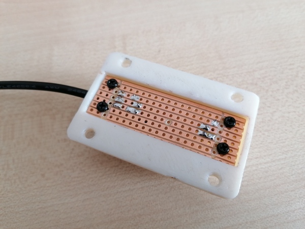
It's just an infrared LED and infrared photodiode facing each other, and a couple of resistors, on a piece of stripboard, inside a 3d-printed housing. The slotted disc will run in the gap between the LED and the photodiode so that it intermittently blocks the light path, which allows me to count the pulses to work out the angle the crank has rotated at any given time.
The mounting holes on the plastic housing will eventually be used to screw the sensor to a piece of material that will hold it in place near the engine.
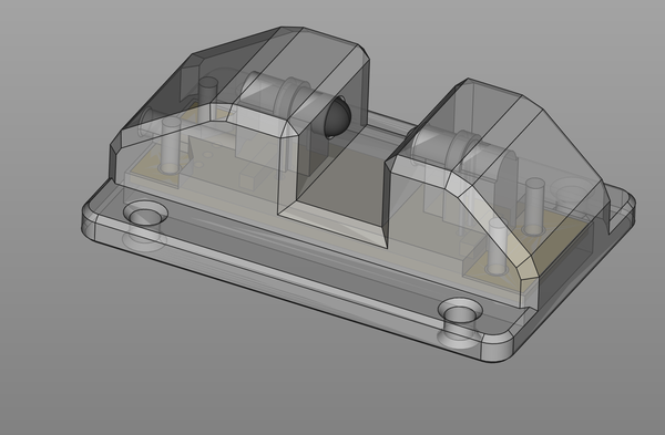
There is a small amount of strain relief on the cable when the PCB is screwed down, you can see in this CAD screenshot:
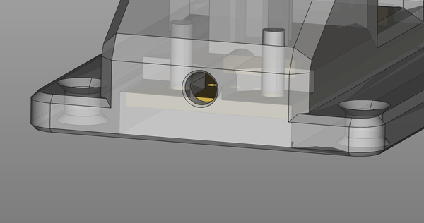
As the PCB is screwed down ("up" in the pic), it clamps the cable into the housing.
The IR LED is powered by 5v and has a 510 Ohm current-limiting resistor. The photodiode has 5v applied to the positive side, and the negative side is the "signal" output. The signal is pulled to ground with a 680 KOhm resistor. This signal pin goes to a digital input pin on the Arduino.
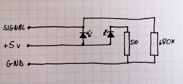
At first I thought I was going to have to use an analogue input and manually configure a threshold value to distinguish "light" and "dark" readings, but the voltage difference between light and dark is almost the entire 0v to 5v range, so it works plenty well enough connected to a digital input.
Some of the schematics available online involve using the photodiode to control a transistor to provide 5v to the microcontroller, but I found this not to be necessary. Probably I am in the easy case because my LED is so close to my photodiode; if you were trying to receive instructions from a television remote control from the other side of the room you would get much less signal. The method I ended up using is from an IR Photogate Instructable.
What didn't work was to use one of these "infrared receivers":
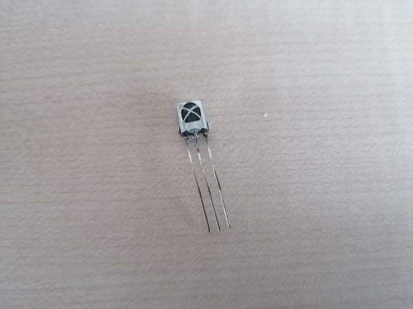
These detect infrared sources that switch on and off at 38 kHz, and the output goes low when it detects a 38 kHz signal and high when it doesn't. I thought this would be easier than using a photodiode (even though I need to make a 38 kHz signal instead of a solid light source) as I thought the photodiode would be too analogue and annoying. The issue I found with the "infrared receiver" is that the output seems to go high again after about half a second, even if the 38 kHz signal remains present. I guess these things are intended to be used for brief bursts of communication, which will involve the 38 kHz signal rapidly appearing and disappearing. Using the photodiode turned out to be easier.
From some testing by sticking a piece of paper in the gap between the LED and the photodiode, I think this is going to work nicely.