
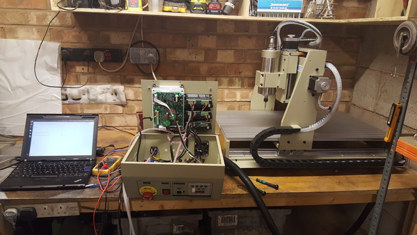
The 6040 CNC machine comes in 2 flavours: parallel port and USB. I don't have a parallel port on the laptop I was intending to operate it with, so I chose the USB option. This is possibly a "mistake" as the USB option uses a proprietary USB interface board which is only compatible with Mach3 and therefore only compatible with Windows. But now that I've got it set up with Grbl, I think I prefer this system to what I would have with a parallel port controlled by LinuxCNC.
I understand that Mach3 normally works by writing step/direction signals to the parallel port. The USB interface board that comes with the 6040 CNC machines has a driver that Mach3 uses to speak USB instead. LinuxCNC also normally works by writing step/direction signals to the parallel port but there is no Linux driver for this proprietary USB thing.
The LinuxCNC forums are full of people trying to operate USB machines with LinuxCNC and being told that USB is not a sensible way to operate a CNC machine because USB is not sufficiently real-time. I disagree. I think LinuxCNC and parallel ports is not a sensible way to operate the machine because Linux is not sufficiently real-time, USB or not. In my opinion, motion control should be offloaded to a microcontroller, and then the PC doesn't need to pretend to be a real-time system, which is exactly the way Grbl does it. Grbl is a motion control system that runs on an ATmega328p (e.g. an Arduino). It takes G-code over USB serial and writes step/direction signals to the GPIO pins.
So let's assume you've got your 6040 CNC machine, and you're onboard with the idea that Grbl is the best way to control it. What do you need to do?
You have 3 main tasks:
- install Grbl on an Arduino
- get Grbl controlling the stepper motors
- get Grbl controlling the spindle speed
Safety notices
Don't do anything dangerous. If you do do anything dangerous, don't get hurt. If you do get hurt, don't blame me.
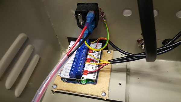
Before doing any work inside the case, you must unplug the power cable (or at least switch it off at the wall, not on the case of the controller) and wait for all of the lights inside the controller to turn off. There are some quite large capacitors in the power supply so it takes a long time for everything to discharge. You must disconnect the power, don't just switch it off on the controller, because there are wires running from the power socket to the power switch that are still live even when the switch is off. I got lazy, and then I accidentally leant on the back of the power socket and zapped myself. Just unplug it at the wall and save yourself the bother.
It's not really necessary to screw the case back together every time you want to quickly test something, but do note that the case is grounded in the top half, but the power supply etc. is connected to the bottom half, so when the case halves are not connected together the power electronics are not grounded.
If you just need to do software stuff then it is not necessary to power up the rest of the machine. The Arduino is powered over USB so it is running when the USB cable is plugged in even if the rest of the controller is turned off.
Also note that the spindle motor is powered by AC as well so try not to touch those wires.
Finally, note that the emergency stop button (in both the factory-supplied configuration and the configuration I'm going to suggest here) does not turn off the spindle motor if the spindle is in Manual mode. In my view, the emergency stop button should immediately cut power to the entire machine, in all circumstances, rather than providing a logic signal to the motion controller. But that's how it is. Shouldn't be a problem as long as you're aware of it.
1. Install Grbl on an Arduino Uno
Download Grbl and run make. If you're on Ubuntu you'll need to install the avrdude, gcc-avr, and avr-libc packages. I used the Grbl code from commit eefe2bb95bb7b21ec2bb87e6ab6e20747e1626c4 which is the latest at time of writing and was published over a year ago. I don't know how likely it is that there will ever be any more changes to Grbl, it seems pretty complete.
The Grbl instructions say that you can import Grbl into the Arduino IDE and then compile and upload it using the IDE. This does work but means you won't be able to conveniently change the code because Arduino takes a copy of it and hides it away somewhere. I spent quite some time wondering why my code changes were being ignored when using the IDE, until I found that compiling on the command line works fine. I'd recommend compiling on the command line. But you probably won't have to make any code changes unless you want to control the spindle speed using Grbl.
I used make to build Grbl, and then this command to upload the binary from grbl.hex to the Arduino Uno:
$ avrdude -v -patmega328p -Uflash:w:grbl.hex:i -carduino -b 115200 -P /dev/ttyACM0This is different to what is listed in the Flashing Grbl to an Arduino instructions. If mine doesn't work for you, try those instructions instead.
With Grbl installed on the Arduino, you should now be able to download and run the Universal G-code Sender and connect it to the Arduino. You'll want to select 115200 baud. If you connect it to Grbl and you get a bunch of stuff written to the console, it's probably working. You can send "$$" to get it to dump its configuration. If that works, you're done installing Grbl and can proceed. If you can't get UGS to work for whatever reason but want to test Grbl anyway, you can use the Serial Monitor in the Arduino IDE. Set it to 115200 baud and send "$$".
I don't know if UGS is the best GUI for Grbl, but it seems to be the most popular. Candle is another option, but I haven't tried it yet.
You'll want to be able to conveniently connect wires to the Arduino, so I recommend getting a "Grbl shield". There seems to be 2 types of Grbl shield available, one just has screw terminals for connecting to external stepper drivers, and the other has integrated stepper drivers. You want the one with screw terminals, because the integrated stepper drivers appear not nearly powerful enough to run the 6040. Get one like this:
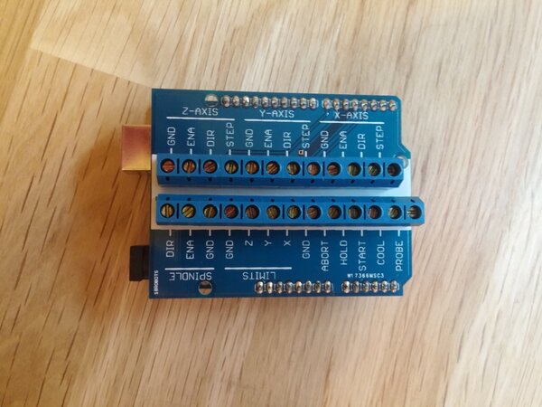
Or just manage without, up to you. All it does is make it easier to connect wires to the Arduino pins. On the bottom side I found some solder jumpers to select between "traditional" and "PWM" spindle control mode. Since we're using a non-ancient version of Grbl, we want the "PWM" solder jumpers bridged together.
2. Connect stepper drivers to Grbl
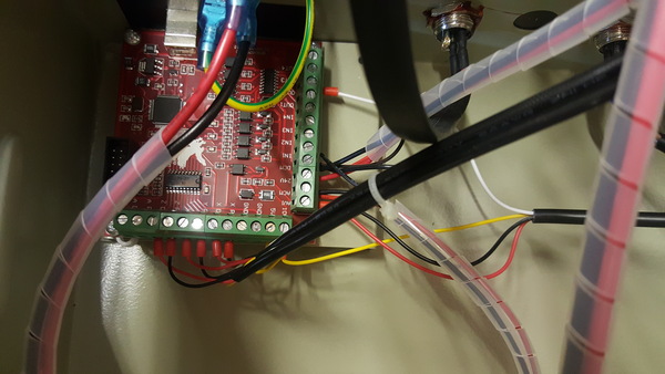
At this stage you should probably take photos and write notes so that you can remember exactly how everything was wired to the original USB interface board. Then you can take the USB board out and throw it away. With all of the wires unplugged from the original board, the emergency stop button is no longer connected to anything, and the case fan is no longer powered. Neither of these are a problem while testing as long as you are aware of them.
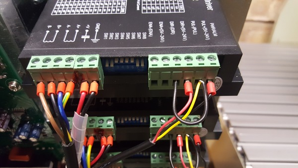
The 6040 CNC has 3x DM542 stepper drivers. Initially the "PUL+" and "DIR+" pins were linked together to +5v, and "PUL-" and "DIR-" were driven by the USB board. I had a bit of trouble getting Grbl to drive it like this, but after I image searched for something like "arduino dm542 wiring", I found this image:
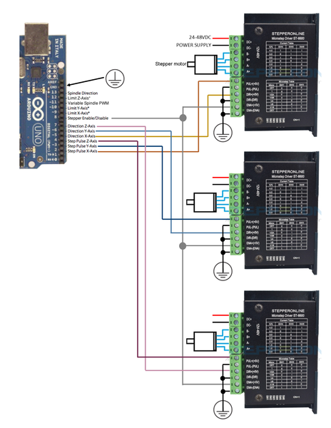
I updated the wiring on the stepper drivers so that "PUL-" and "DIR-" were wired together to ground, using the yellow wire to connect to the ground pin on the Grbl shield, and "PUL+" and "DIR+" were driven by Grbl. This worked straight away, great success. I left the enable pins ("ENA+" and "ENA-") disconnected like they were before. This seems to work fine, the steppers are just always enabled.
If it helps, you can unplug the screw terminals from the stepper drivers. This makes it much easier to access the screws.
With the stepper drivers plugged in and wired correctly, you should be able to use G-code to move the axes. Either manually send a command like "G0 X5", or use the GUI to jog the axes. If they all move some distance in some direction when prompted, then you're golden. If not, there is probably some wiring mistake.
Finally we need to configure the direction, steps/mm, max. velocity, and max. acceleration for each axis. Type "$$" in UGS to get the configuration values back out. You can also read the Grbl v1.1 Configuration documentation to learn how to set it up.
I went with:
| Setting | Value | Meaning |
|---|---|---|
| $3 | 7 | Step direction invert (bit mask) |
| $100 | 320 | X Steps/mm |
| $101 | 320 | Y Steps/mm |
| $102 | 400 | Z Steps/mm |
| $110 | 8000 | X max. speed, mm/min |
| $111 | 4000 | Y max. speed, mm/min |
| $112 | 200 | Z max. speed, mm/min |
| $120 | 100 | X max. acceleration, mm/sec2 |
| $121 | 100 | Y max. acceleration, mm/sec2 |
| $122 | 100 | Z max. acceleration, mm/sec2 |
To update a setting, send something like "$100=320". This gets stored permanently by Grbl (either in EEPROM or flash, not sure) so that it is not lost across a power cycle.
I roughly "binary-searched" to find the max. speed for X and Y axis, and then set the limit to a few thousand mm/min short of what it takes to stall the motors. For the Z axis I deliberately set the max. speed very low, because a fast-moving Z axis is not particularly useful, and a slow-moving Z axis gives you a chance to hit the emergency stop button before the end mill snaps.
With the steps/mm configured, you should be able to measure that each axis moves the correct distance when jogged. Be wary of trying to tune these values "more accurately", you will likely only make it worse. For example if you measure that the X axis moves 100.3 mm when you ask for 100.0 mm, it is more likely that your measurement is off (e.g. not perpendicular to the axis) than that the steps/mm needs adjusting. The correct value for steps/mm is simply a function of the pitch of the leadscrew, the number of steps for a full revolution of the motor, and the microstepping mode of the driver.
3. Wire up the case fan and emergency stop
At this point the wires powering the case fan are not connected to anything, and we also have spare +24v and ground wires from the DC power supply. I just soldered the fan wires to the power supply wires, but a screw terminal block would do. 24 volts seems like a lot for a case fan, but it was running off 24v in the factory configuration, so it's probably fine.
The emergency stop button is a "push to make" switch, which means the terminals are connected together when it is pushed in. To make the emergency stop work, just connect one side of the switch to a ground pin on the Grbl shield, and the other side to the Abort pin on the Grbl shield. This means the Abort pin is pulled to ground when you push the emergency stop button. Verify that it works: start a long slow movement of the Y axis, for example, and hit the emergency stop. The motor should immediately stop moving, and Grbl should enter an Alarm state which will be indicated in the GUI.
4. Program the VFD
The spindle speed is controlled by a device called a "PRT-E1500W". This is a VFD or variable-frequency drive. The eBay listing for my machine said:
Please don’t change the data setting of the VFD if you are not professional technicians, or it might damage the spindle motor.
I'm not professional technicians, so I was planning not to change the data setting of the VFD, but when the machine arrived, the VFD was not programmed correctly. It would not work even in Manual mode. I don't know why.
I followed these instructions (mirrored) from madexp to program the VFD, but note that after step 1b (D176=1, resetting to factory settings) you must again set D001=1 to unlock the rest of the settings. You only need to go as far as completing step 3. I don't know what step 4 means. I completed step 5 (display RPM instead of AC frequency) as well because it seems helpful. Steps 6 and beyond appear to be purely Mach3-specific.
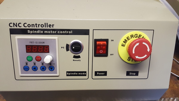
Once you've programmed the VFD correctly, you should be able to select "Manually" mode, press the green "Run" button, and use the knob on the panel to change the spindle speed. If that works and is enough to satisfy you, then you could quite happily run G-code all day long with Grbl controlling the stepper motors and you manually selecting the spindle speed.
But I like a challenge, so I wanted Grbl to control the speed.
5. (Optional) Connect VFD to Grbl
Controlling the spindle speed with Grbl is the hardest part. If you just connect the spindle enable pin to the "AVI" pin of the VFD, you will be able to control the speed but only up to half of the maximum speed. This is because the VFD expects a 10v signal on AVI and the Arduino can only supply 5v. I solved this by using a pair of transistors to let the 5v signal from the Arduino switch 10v to AVI, so that we can get Grbl to effectively generate a 10v PWM signal from its 5v output. Here's the schematic I came up with:
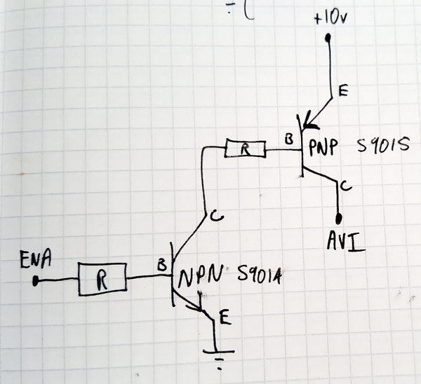
I used an S9014 and S9015 transistor because I had them convenient to hand, but you should be able to use anything that can handle 10v. I used 4.7 kOhm base resistors. The schematic should be fairly self-explanatory. I explicitly labelled emitter, base, and collector because I can never remember which is which. The +10v supply comes from the yellow wire from the VFD, AVI is the red wire to the VFD, ENA and ground are on the Grbl shield.
I put this together on a little piece of stripboard with some screw terminals:
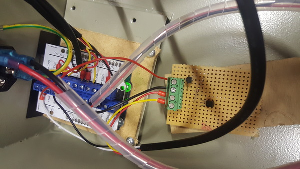
And wired it all in, and it worked! I was now able to select the entire range of spindle speeds. I screwed the stripboard to a piece of plywood and glued the plywood to the inside of the case, to prevent it from flapping around.
To request a spindle speed with G-code, send "M3" to turn the spindle on, followed by (e.g.) "S5000" to request 5000 rpm. "M5" turns the spindle off, as does "S0". "M4" asks for the spindle to turn backwards. I found that this didn't work, it still turns the spindle forwards, even though I connected the direction pin to the VFD. I'm not sure I'd ever want to turn the spindle backwards, but maybe that's worth looking into if I ever do.
But there was still a problem: when I requested 5000 rpm the VFD reported that it was providing about 6400 rpm. If you're fine with that, you can stop now and you're done, you'll just have to have a mental calibration curve for the rpm requested vs. received.
But my view is that this is a job for the computer, not the human, so I wanted to modify Grbl so that it did the calibration curve for me. This blog post details modifying the Grbl source to use a custom function for the PWM output. I started trying to derive a function for the curve, but then stumbled across Grbl's built-in "piecewise linear" function support for non-linear spindle speeds. Just read through the comments in doc/script/fit_nonlinear_spindle.py in the Grbl repo and it tells you how to use it. You'll need scipy (e.g. python3 -m pip install scipy) for the calculation, and matplotlib if you want a plot of the fit. Here's what the fit_nonlinear_spindle.py output looked like for my machine:
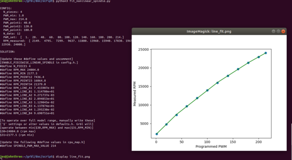
And then with the suggested changes made to config.h and cpu_map.h, and the suggested settings for $30 and $31, the VFD-reported spindle speed matches my requested spindle speed to within a few hundred rpm throughout the entire range. Great success! Remember that if you are modifying any of the Grbl code, you'll need to be compiling on the command line and not in the Arduino IDE.
Now I just have to learn how to actually use this machine to make parts...
Contact me
If you used this information to convert your 6040 CNC machine to Grbl, please email me to let me know.
Also, if you are confused by any of the information, or if you can provide more accurate information, please let me know that too!