
I'd like to build a high-resolution grid of tiny electromagnets. It would work a lot like an LED matrix display, except instead of the pixels emitting light, they emit magnetic fields. I have made a small proof-of-concept, but I need help to learn more physics to improve the strength of the field and the density of the pixels.
Here's a video demo of what I have so far. When you watch the video, just use your imagination and visualise the same sort of thing, except the electromagnets are really small and powerful, and there's maybe 64*64 of them, and they're switched automatically by a microcontroller instead of by hand.
The idea for this project came from the Regium KickStarter scam. Regium is an automatic chess board. I actually built an automatic chess board myself. Like most of the commercial equivalents, my board used a single electromagnet on an X/Y motion stage to move the pieces around. In contrast, Regium claimed to have a high-resolution grid of tiny electromagnets just underneath the playing surface. This would allow them to move the pieces around silently, to move multiple pieces at once, and to hold all of the pieces in place while you move the board around so they don't fall over. The only downside is it doesn't exist.
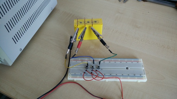
But I love the idea and I want to see how close it is to being possible, so I made a few electromagnets and connected them up in this 3*1 "grid".
Shortcomings
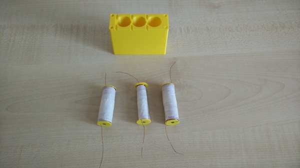
I wanted to make an actual grid for the proof of concept, even if only 2*2. But I did a handful of small experiments to decide how much wire to put in one electromagnet, and it turned out I only had enough wire for 3 of them. And I actually ran out before the 3rd one was done, so the middle one is smaller.
So in the absence of more wire, a 3*1 grid will have to do.
The electromagnets that I have made so far are both too large and too weak to make an effective chess board. The bobbins are 16mm diameter, and the housing puts the electromagnets 18mm apart. At 10v the 2 larger coils draw about 350mA and start to get warm if switched on for a while, so I wouldn't want to put any more current through them. They're barely strong enough to pull the steel ball around, let alone slide chess pieces across a board.
I did find that the smaller coil, drawing 660mA at 10v, is actually stronger than the larger coils, although it heats up even faster. Maybe the answer is to get some slightly thicker wire and run it at a higher current.
The core is made out of a mystery steel. I have no idea if it is good, bad, or about average for this purpose.
It may well be that it is not actually possible to make a working automatic chess board this way. You need to have either lots of turns, or high current, to create a strong magnetic field, and both of those place physical limits on how small you can make the electromagnets. It's quite possible that the achievable resolution is just not good enough.
Questions
I think this project would benefit from knowing the answers to some/all of the following questions. If you know the answers, or know someone who does, please email me: james@incoherency.co.uk.
- How do we quantify how effective a candidate material would be to make the core out of? I want to be able to compare any 2 different materials, to find out which one is better & by how much.
- What is the best material to make the core out of?
- What is the best wire diameter? You can fit more windings in the same space if the diameter is lower, but you can't put as much current through it.
- Short of adding more turns (makes it larger), or more current (needs thicker wire, which makes it larger), how can we make the electromagnets stronger?
- How much of a difference does the diameter of the core make? We want it small to increase the resolution.
- Does adding turns via more height actually help, or does it just serve to shift the centre of the magnetic field further from the surface?
- Would making the core encompass the outside of the coil be advantageous, disadvantageous, or irrelevant? Note that we want the field to extend away from the surface, we aren't just looking for the highest possible density at points immediately close to the coil.
- How high a frequency do we need to switch the coils on/off if we want the field to stay relatively constant?
- Would adding a capacitor to each coil, to form a low-pass filter, help with multiplexing them?
- What are some potential applications for this technology beyond an automatic chess board?
Commercial electromagnets tend to have the core surrounding the coil except for a small gap at the top, and they also tend not to be excessively tall.
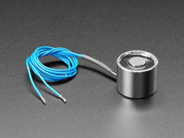
(Pic from Adafruit. The coil is underneath the black seal; the core is the shiny part.)
However, commercial electromagnets are normally aiming to grab things that they contact. They would rather have a very concentrated field right next to the surface of the electromagnet, whereas we would rather have the field extend further away from the electromagnet, even at the expense of field strength immediately adjacent to it. So I'm cautious of imitating the common commercial designs because I think they may be counterproductive for our application.
How I made it
I 3d printed the end caps:
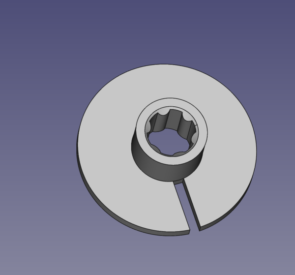
They have a 16mm outer diameter, and the centre is a tight fit on a 4mm core.
I chucked some 4mm mystery steel rod stock in the lathe, slid on a couple of end caps, taped down the starting end of the wire, and ran the lathe, using my fingers to guide the wire onto the core. Here's a clip of that process:
(Yeah, I know, the lathe is dirty and I should clean it).
Having wound the entire coil, I wrapped the windings in tape to stop them coming loose, and then cut the coil free of the rod stock with an angle grinder. I think if I were to make more of these I would cut the cores to length ahead-of-time, and come up with some alternative way of holding them in the lathe while winding the coil. There's too much risk of damaging the wire with the grinder otherwise.
Since I had no natural reference for the relative positions of the 2 end caps, the 3 coils ended up slightly different lengths, so when I 3d printed the housing I compensated for this in CAD:
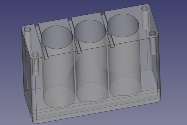
You can see the left hole is shorter than the other 2, which are also not exactly equal. Having printed the housing, we have these parts:
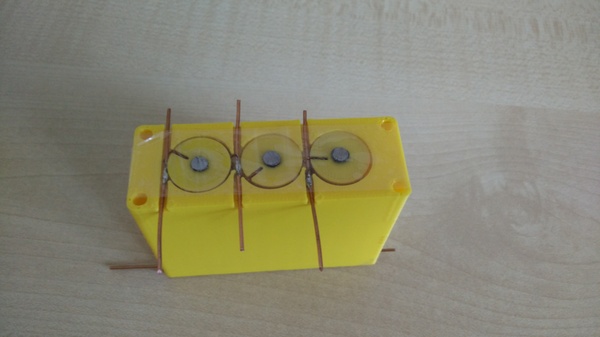
I then dropped in each coil, soldered to copper wires at top and bottom, and wrapped it in sellotape to keep them in place, and to allow the ball to roll around more easily:
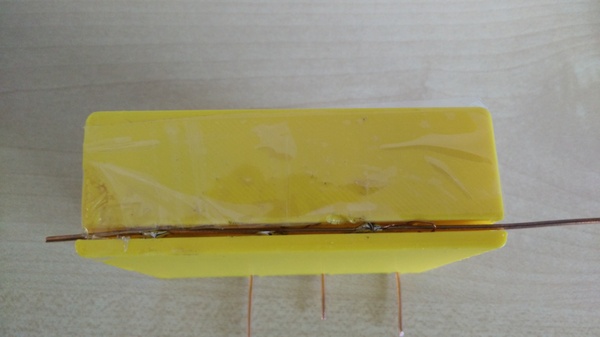
The bottoms of the coils all share a common ground. I would use a similar plan if I were making a "real" grid rather than a straight line. There would be a wire at the top for each column and a wire at the bottom for each row. To energise a single coil, you have to connect that coil's row (for example) to 10v, and its column to ground. Then the only coil that has a complete circuit is the one at the intersection of the selected row and column. The benefit of this is that as the grid size grows, you only need to be able to switch O(n) connections to address an arbitrary coil in an n*n grid.
Finally, I connected some buttons to the coils so that I can power them up independently:
Maglev chess
While talking about this project, Peter suggested that "maglev chess" would be a fun idea. You wouldn't even need it to be automated in any way, I think just the sensation of manually moving chess pieces around on top of a surface that makes them levitate would be fun. I don't know enough physics to know the best way to do it, but I think you'd want the centre of each square to repel the pieces, and the edges of the square to repel the pieces even more strongly, so that the only place for the piece to go is up in the air.
You also need to make sure that the pieces don't fall over, either by putting the magnets at the top so that gravity works for you (but then you need the repulsion to be much stronger), or by having multiple poles on the bottom so that the piece can't tip in any direction.