
I designed a puzzle for an escape room. The company ended up not wanting to pay for it, but I thought the puzzle was interesting enough to be worth making for myself anyway.
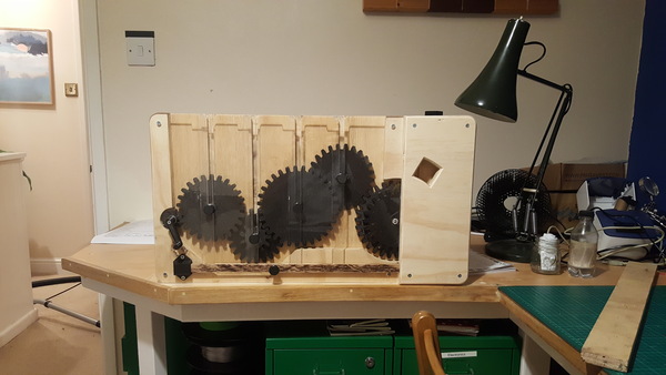
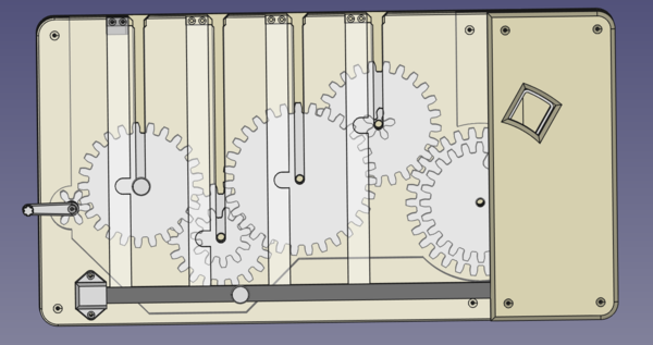
This is what the puzzle looks like:
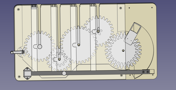
And here's a demonstration of how it is solved:
James suggested calling it "All the gears, no ideas", which is too irresistible a pun not to use.
Prospecting
I like puzzles, I like making stuff, and I like escape rooms. For a little while I've had the idea that I would like to work on puzzles for an escape room. But I really don't want to do this as a job, I'm more after a kind of "paid leisure activity". (If you happen to work for an escape room and you want me to work on puzzles for you, please get in touch!).
In September I sent out a short letter to every escape room I could find in Bristol, with an enclosed 3d printed chess piece explaining that I wanted to work on puzzles for them. The next day there was a bomb scare at a nearby Royal Mail sorting centre, and I wondered if their X-ray machines had mistaken the gyroid infill pattern for some unusual plastic explosive and they had therefore destroyed it, meaning all my efforts had been for nought.
(It actually turned out that the bomb scare was caused by an interesting scam whereby expensive items were sold on eBay, but the shipped package instead contained some sort of chemical reaction which would slowly burn through the shipping label, so that halfway through processing it, Royal Mail would lose the package and would reimburse the seller for the supposed value of the items).
Anyway, I eventually received an email from a person who we'll refer to as Baz. Baz works at one of the escape rooms I contacted, but he doesn't want me to say which one in case customers find this post while Googling it and spoil the puzzle.
Puzzle idea
Baz and I exchanged a few emails about puzzles and escape rooms, and he invited me in for an "interview" of sorts. The day before, he set me effectively the escape room equivalent of a "whiteboard coding" problem. Roughly, it was:
The players will find gears of different sizes lying around the room. Design a wall-mounted puzzle where the players have to fit the gears in the correct order so that cranking a handle on the left turns all the gears, which operates a mechanism on the right. Ensure that the players can't bypass the puzzle by operating the mechanism on the right without using the geartrain.
I designed this:
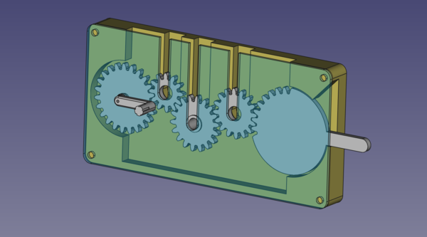
The idea is that each removable gear will be on a shaft, on which it is free to turn but can't fall off. The shaft will sit in the slot cut in the front panel, allowing the player to insert and remove the gears, but not allowing the player to turn the gears without using the cranking handle. I was very pleased with this design and could not see any flaws in it. The arm on the right hand side would be inside a mechanism used to unlock a box or similar. It would not be accessible by the players.
I produced this overnight to show Baz:
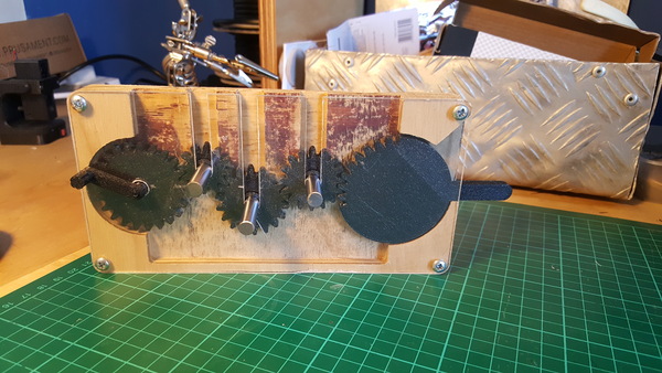
I had quite a bit of trouble cutting the acrylic on the CNC machine. It seemed like it wanted to melt and stick to the tool and lift up off the table more easily than it would cut, but I sprayed a lot of water over it while it was cutting and it came out acceptably.
With the puzzle assembled, I immediately discovered the first flaw: when you try to crank the handle, the forces are trying to lift the clockwise-rotating gears out of the slot rather than rotate them. This should have been obvious. I was pretty disheartened by this flaw, but there was no time to fix it, so I just presented it to Baz anyway. Ruari suggested replacing the slots with circular holes, and then the players have to drop the gears down from the top and skewer them with a shaft through the holes. That would definitely prevent the gears from riding up in the slots, but it adds a bit too much of a "dexterity puzzle" component for my taste.
Jamie pointed out that it might be possible to cheat by putting multiple gears in the final slot and turning them from the top instead of using the cranking handle, and indeed this works :(. So this is another thing to fix.
But it turned out that Baz wasn't expecting much more than a convincing-looking sketch of the design, so he seemed pretty impressed with the demo regardless.
Problems
Baz and I identified the following problems with the prototype:
- the clockwise-rotating gears get pushed up in the slot
- the acrylic is too flimsy because the slots mean there are long thin sections that are unsupported on 3 sides
- should have more than 3 gears to make it a bit harder
- you only get about 1/4 of a turn on the input gear to cover the whole range of the output gear; would be better if the players have to do a decent number of cranks
- the output mechanism should actually do something instead of being an arm connected to nothing
- you can cheat by putting multiple gears in one slot
Your first thought for stiffening up the acrylic might be to add a support at the top, but this won't work because it prevents the gears from fitting. The gears mesh against each other, which means the rightmost coordinate of one gear is further right than the leftmost coordinate of the next gear. This means there can never be any place to put a support that doesn't interfere with the insertion of the gears.
So then we thought we would angle the slots so that the gears on the left slide down towards the right and the gears on the right slide down towards the left, and then there is scope to support the acrylic in the centre. We also thought we could add a CNC-cut wooden frame around the perimeter of the acrylic to stiffen it up.
I quoted £100 to construct a second prototype of the puzzle solving these problems, but Baz's bosses thought that was too expensive in light of the fact that they were closed indefinitely due to the coronavirus laws. So they did not want to pay me. However it turns out I underestimated how much more work the second prototype would be than the first, and £100 was way too cheap.
But at this point I was far too invested in the puzzle to stop working on it, so I made one for myself anyway. And since I'm not going to have daily consecutive crowds of rowdy hen parties trying to break the puzzle in my house, I relaxed the requirement to support the acrylic and instead just used the same slot design but with thicker material.
Calculating gear sizes
One thing I didn't like about the first attempt is that I just guessed the gear sizes and roughly lined everything up so that it looked like it fit together. It did work but you can do better.
Involute gears use a tooth profile that maintains a constant pressure angle throughout their rotation, which means the gears have a fixed speed ratio (the gear ratio), with no speed changes throughout the meshing of each tooth pair, as shown in this animation:
(Image from Wikipedia.)
The contact point of the 2 meshing teeth always lies on a line that is tangent to the base circles of the gears, and the force applied is always in the direction of this line.
The involute gear profile was a fundamental advance in machine design, since unlike with other gear systems, the tooth profile of an involute gear depends only on the number of teeth on the gear, pressure angle, and pitch. That is, a gear's profile does not depend on the gear it mates with. Thus, n and m tooth involute spur gears with a given pressure angle and pitch will mate correctly, independently of n and m. This dramatically reduces the number of shapes of gears that need to be manufactured and kept in inventory.
from Wikipedia.
If you imagine 2 gears meshing together as 2 smooth wheels, then the wheel with the same effective diameter as the gear is the pitch circle, and the diameter of this wheel is the pitch circle diameter.
(Image from MiSUMi Mech Lab.)
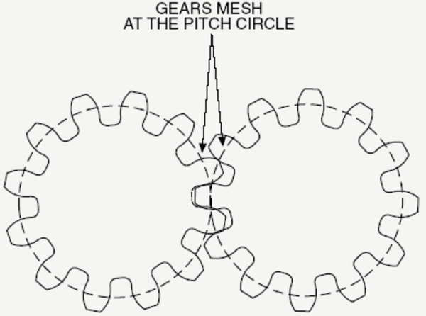
Gears are sized by their "module". The module is defined as the ratio of the pitch circle diameter to the number of teeth. Although the module effectively describes the size of the teeth (in the sense that 2 gears with the same module will have the same size teeth), it is not something you can find by measuring the teeth directly.
The pitch circle diameter of a gear is the module multiplied by the number of teeth. Once you've settled on a module (I used 5.25 mm), and a number of teeth for each gear, you can calculate the exact pitch circle diameter for each gear, and therefore the required distance between 2 gear centres to make the gears mesh together perfectly.
To get the gear reduction from left to right, I made each piece actually have 2 gears on it, fixed together, with the small gear of each driving the large gear of the next, and with the gears alternating between having the small gear at the front and the large gear at the front. This presents a bit of a problem because you need to make sure that each piece's large gear doesn't crash into the small gear of the next. I discovered that I needed a safety margin of 5 teeth before 2 gears wouldn't crash into each other. I.e. if gear A has 20 teeth and gear B has 30 teeth, then to put a smaller gear in the position of gear B and have it not interfere with gear A, the smaller gear would need to have no more than 25 teeth. It's not obvious to me whether the margin of 5 teeth is a general property of involute gears or if it is related to the module size. Seems like it would be a general property, because increasing the module size increases the size of the gear linearly.
I wrote a quick Perl script to search for a set of teeth that would make the puzzle possible to assemble, with sensible-sized gears, without any unwanted meshing or interference, and with at least 2 different ways to mesh a gear with both the input and output gear of the puzzle, to increase the number of ways to incorrectly half-solve it. There were a decent handful of solutions, so I selected one that made the distance between each pair of gears as close together as possible, to maximise the number of ways they could plausibly be inserted. If you read through the program, you might think it is unsound that I'm adding tooth counts together and comparing them as if they are diameters. This actually works perfectly fine, because the diameter of a gear is just the number of teeth multiplied by the module. Since all the gears use the same module, we can just assume a module of 1, and the maths all works out the same.
The tooth counts I ended up with were:
| Gear | Big gear | Small gear |
|---|---|---|
| A | 25 | 20 |
| B | 21 | 11 |
| C | 31 | 16 |
| D | 25 | 5 |
CAD
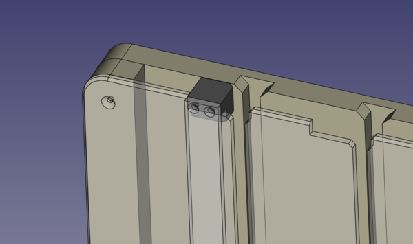
With the tooth counts decided, it's time to CAD the parts. I started with a "master sketch" to define the locations and sizes of the gears and backplate. The circles here represent the pitch circles of the gears (with a little bit extra diameter to make sure there is enough clearance for them to turn without binding).
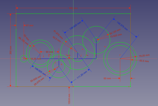
The master sketch isn't directly used to make any of the parts, it just makes it a lot easier to reference the same locations and dimensions when designing the other parts.
You can see in the master sketch that each small gear drives the next big gear, except for the final gear. The small gear on the final removable gear does not mesh with anything, it is just there so as not to make the final gear too obvious. The small gear on the output gear is sized so that it is able to mesh with one of the other gears, so that it is possible to make a wrong choice and still get it to mesh correctly (although this would preclude the solving of the rest of the puzzle).
Two of the removable gears have the big gear on the "outside", and the other two have it on the "inside". It is not possible to put a gear in the wrong way because the handle does not fit in the slot on the inside. Stavros pointed out that I should have made the shafts symmetrical so as not to give any information about which way around each gear must go. I don't actually know why this didn't occur to me, but it would definitely be an improvement.
To prevent the players from putting more than one gear in a single slot, I added the "slot blockers" which can move left and right with the sliding bar. With the bar in the left position, the players are free to move gears up and down in the slots, but the output gear will not move because it is locked by a plastic piece at the end of the bar. With the bar in the right position, the output gear is free to turn, but the gears can not ride up in the slots, and the players can not put extra gears in the slots, because they are blocked off.

I discovered that the slot blockers would not quite be enough to prevent the players from cheating by reaching down with a larger gear, so I added "top blockers" as well. These are plastic pieces connected to the top of the slot blockers that block off the top of the slot and completely preclude reaching down with a larger gear.
Finally, rather than have the puzzle operate some unspecified locking mechanism for a box, I made it raise a little "shelf" up to an access hatch. The shelf can contain a small key, a clue, or some other object that progresses the room.
The CAD files (including STL files for 3d printed parts, and CAM setups for CNC parts) are available on github.
Construction
The 3d printed parts are all in Prusament Galaxy Black PETG. I really like how this material looks, but it seems much more brittle than other PETG filaments I have used. Not sure what's going on there. Most of the CNC parts are made out of 19mm plywood. The plywood is not very good quality, I should really try and source some "baltic birch" plywood for stuff like this in the future. The sliding bar is made of oak. I cut the outer dimensions of this on the table saw, but I left a lot of burn marks and made a real mess of it. I've been using the tablesaw to cut brass and aluminium, so probably the blade is getting blunt.
The clear plastic front panel is 5mm polycarbonate. I used polycarbonate because it is less brittle than acrylic, and also because I found a good deal on large sheets of it on eBay. This time I searched online to find suitable speeds and feed rates for cutting polycarbonate, instead of guessing, and it cut a lot more easily than the acrylic did. Mainly this involved much lower spindle speed and faster feed rate.
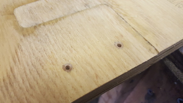
I used a chamfering tool on the CNC machine to mark the centres of the holes that I needed to drill, but drilled them by hand because I have so far had poor results trying to drill small holes with the CNC machine, that's something I need to work on.
I made a bit of a blunder in drilling the holes by hand, in that I accidentally drilled them all as clearance holes, instead of using a smaller drill for the ones that I want screw threads to bite in. D'oh! Martin suggested drilling them out even larger, gluing in dowels, chiseling them flush, and then re-drilling the correct size. This worked well, great success, crisis averted:
Towards the very end of putting it all together, I realised that I had made a fatal design flaw! The small plastic "top blockers" actually block the insertion of the gears even when the sliding bar is in the leftmost position:
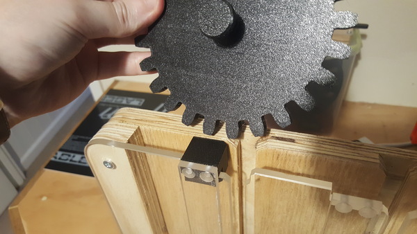
What a stupid mistake! This should have been obvious much sooner. The top blockers can't work for exactly the same reason that the clear panel can't be supported: the entire width of the top needs to be open else the gears can't be inserted.
So for now I have just removed the top blockers. The rest of the puzzle works, but it can be easily defeated if you install the final gear correctly, and then operate it by reaching down from the top with the largest gear.
Further work
I think the puzzle as it stands is OK, but not great. The vulnerability that lets you solve it by poking the large gear down from the top is what breaks it, really.
I think you could turn it into an acceptable escape room puzzle by increasing the height of the clear panel so that it is not possible to operate any of the gears with another gear at the top, but I think there is probably scope for a more elegant solution if you go back to the beginning and rethink the whole thing. The business about using the sliding bar to block off the slots and stop the output from turning seems inelegant. I would be interested to see designs (or implementations!) for superior versions of this puzzle.