
We could automatically detect whether the racing mower is about to run out of fuel by shining a light through a section of clear fuel hose with a sensor on the other side. The idea is that when the fuel has disappeared the received light intensity will change, and we can detect this with a microcontroller. We can then turn on an LED on the dashboard to alert the driver so that he makes a pit stop instead of spluttering to a halt at the opposite end of the track.
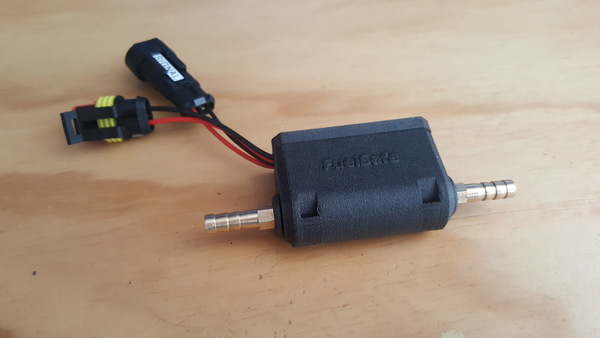
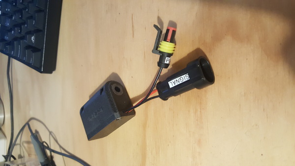
I wasn't able to find any examples of previous attempts at something like this, DIY or otherwise, which most likely means it is a bad solution to the problem. But I made it, and it works. Here's what it looks like:
If you want to see a video of it in action, I have this video but it's not a very good video.
You can get the Arduino code and housing CAD files on my github project.
This is a good design for the fuel sensor, in my opinion, because the fuel is entirely contained within off-the-shelf parts that are designed to contain fuel and never touches any custom parts, which means the chances of causing a leak or fire are low. The bad part about this design is that it does not give us an easy way to configure a threshold at which the warning light comes on: it just comes on once the fuel level has dropped below the position of the sensor. But I think this should still give us a lap or two of warning, because we still have the fuel in the rest of the hose, the fuel filter, and the float bowl.
Experiments
I didn't want to commit to making the entire thing before discovering whether or not it would even work. For example, it's quite possible that the brightness detected at the photoresistor would be within the same range regardless of the presence or absence of fuel.
I set up a short length of clear hose with some water in it, and 3d printed a little ring that would allow me to position an LED and photoresistor at different relative angles. I used water because I didn't have any convenient petrol to use, and water is clearer than petrol, so if it works with water it should definitely work with petrol.
I measured the "reading" from the photoresistor by setting up a voltage divider with the photoresistor on one side and a 4.7 kOhm resistor on the other. I chose a green LED because I read that photoresistors are most sensitive to green light.
My initial thought was to shine the LED straight through the hose, but I thought that refraction and reflection might provide interesting effects and we might get a different "signal strength" if we changed the angle, which is why I tested 4 angles. As it turns out, we do:
(As an aside: both of these charts have the angles in the correct order, but at incorrect labels; the actual angles tested were 60°, 100°, 140°, and 180°, but I had a thinko each time when writing the data in the spreadsheets).
For the first test, I didn't even switch off the lights in the room. I just moved the ring up and down between water and air, and recorded the rough range of measurements at each position. The "error bars" here show the range of values I recorded.
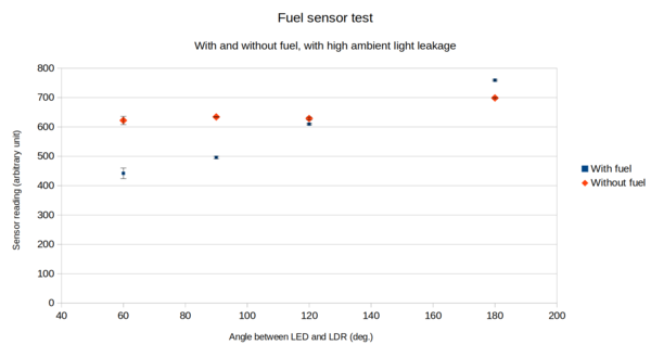
It turns out that any of the possible positions appears to have sufficient discriminatory power to work as the actual sensor, as they all had no overlap in readings between the "with fuel" and "without fuel" conditions. I repeated the test with the lights in the room switched off, and got similar results:
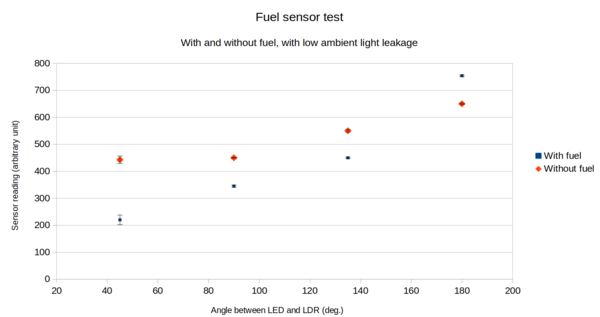
It's interesting that somewhere between 140° and 180°, the brightness "with fuel" goes from being lower than "without fuel" to being higher.
From these results, I concluded that the 60° angle is the best choice because it has the widest gap in sensor readings between the "with fuel" and "without fuel" conditions.
Housing
I wanted to run this off an ATtiny85 microcontroller, because they are small and cheap, and I haven't managed to use one for anything before. Using an ATtiny85 means we need to expose a 6-pin programming header. It took me quite a long time to come up with a neat way of packaging all the parts so that:
- the fuel hose runs straight through
- the fuel hose does not fall out
- the electronics can easily be potted in without spilling resin everywhere
- the programming header is protected from damage
- the device is firmly held and not just flapping around loose
- the parts 3d print without excessive support material
I eventually settled on this, which looks obvious in hindsight, but was hard for me to think of:
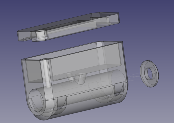
The fuel hose runs through the cylindrical hole at the bottom. The small end cap prevents ambient light from leaking up the length of the hose (there'll be one at each end, but I only modelled one as they are both identical). The LED and photoresistor get glued into the little holes that meet the large cylindrical hole. The circuit board sits in the cavity at the top. The flat lid piece screws down into the housing to protect the exposed programming header and provide a flat surface to mount against the chassis of the mower, and the cut-outs through the bottom allow cable ties to strap the device in place.
I also added a small logo because I was feeling fancy:
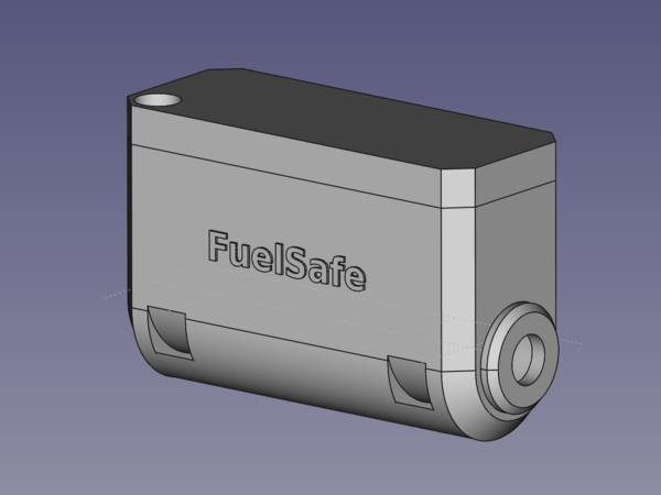
I 3d-printed this in 3DXTech's CarbonX Nylon. Pretty much any material would do as these parts are not really under any load, but carbon fibre gives you automatic racing credentials so it was the obvious choice.
The writing is not as easy to read as I had hoped.
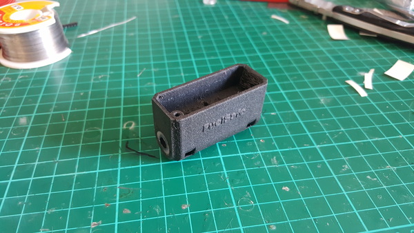
You can see there that I have already pushed the clear fuel hose into the hole. This was an extremely tight fit so I am not at all concerned that it might fall out.
The screw hole does not have printed threads, I just cut a thread in it by hand using an M3 screw.
Electronics
I designed the circuit board in tandem with the housing, because the plan for each one informs the design of the other. Here is what I came up with as a "schematic":
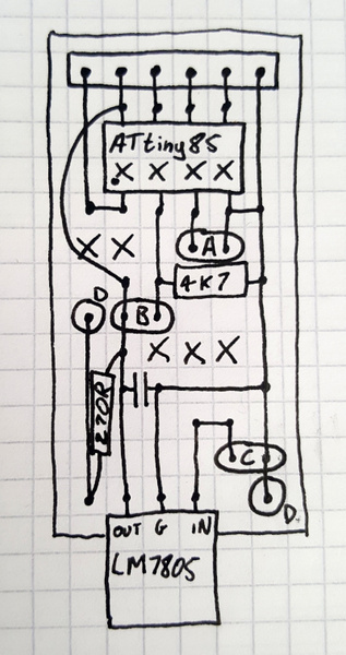
In addition to being an almost-adequate schematic, it also doubles as a copper stripboard layout, which is why it is laid out so strangely and also why it has some crosses, marking where traces need to be cut. The A,B,C,D labelled connections are:
- A: output signal and GND
- B: to photoresistor next to hose
- C: input power and GND
- D: to LED next to hose
It uses an LM7805 to regulate the input voltage down to 5v. There is an arbitrary smoothing capacitor across the output of the LM7805 for good measure. I picked a small ceramic capacitor when I put it together, but I have no idea how much good it will do. The 6-pin connector at the top is a programming header for the ATtiny85.
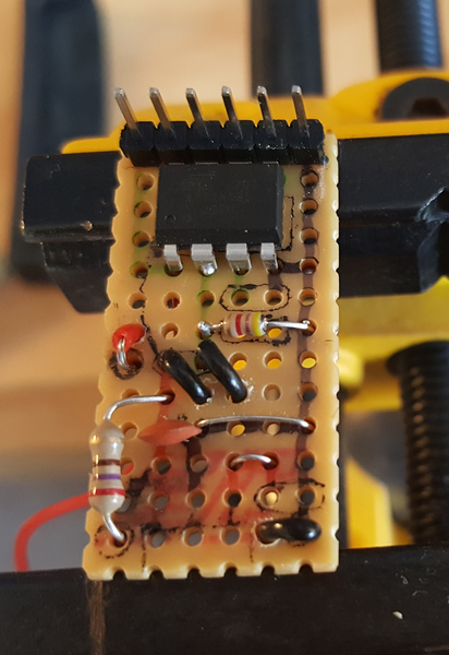
Here's a picture of the board with the "C" and "D" wires in place, but "A" and "B" not yet, and also the LM7805 hadn't arrived yet:
This project could have been quite a bit smaller if I had used SMD components on a custom PCB instead of through-hole components on copper stripboard. I have never made anything with SMD components but last time I showed Stavros one of my projects he remarked "you really like through-hole, huh?". I think it is probably about time I learnt how to do SMD. Maybe next time.
The software running on the ATtiny85 is very simple. It just runs in an infinite loop, comparing the voltage on an analogue pin to a threshold value, and switching the output signal on if the threshold is exceeded, and off otherwise. This could be replaced with a comparator quite easily. I didn't do it that way, for two reasons: firstly because software makes more sense to me than electronics, and secondly because the microcontroller can be reprogrammed with whatever logic we can think of in the future, and the comparator can't. For example, if we find that the signal is too noisy, it is easy to add some smoothing logic in software, but it's not easy to add extra components to the circuit board.
Assembly
With housing and electronics ready, we can start putting this together. I epoxied the LED and photoresistor into their holes with clear epoxy, rather than just letting the potting resin hold them in place, because I was planning to use black polyurethane resin for the potting, and I was concerned it might inhibit light if it seeps around to the front of either the LED or the photoresistor.
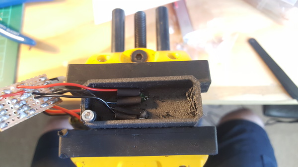
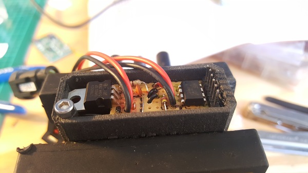
Then push the circuit board into its cavity:
Then we just have to pour the resin. I was disappointed to find that the bottle of hardener for my polyurethane resin has all crusted up and set solid, so I wasn't able to use it. I couldn't be bothered waiting for some new resin to arrive, so instead I used the extremely soft 2-part silicone resin that I bought for making the tyres on the antweight combat robot. This is a bad choice of potting compound because it is not very good at preventing sharp objects from penetrating it, and it does not stick to stuff. But with the lid on the housing, I think it'll be fine.
Protip: if you're potting some electronics, and you want to expose a pin header, use a male header instead of a female one, otherwise it might fill up with resin.
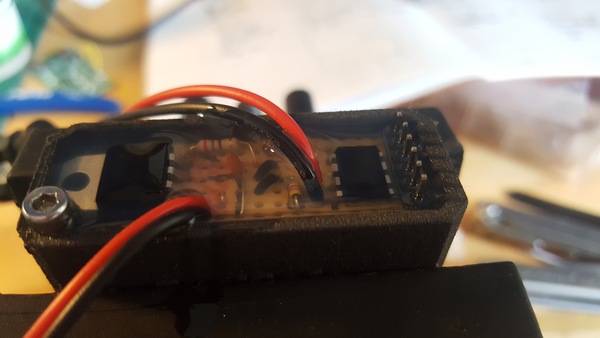
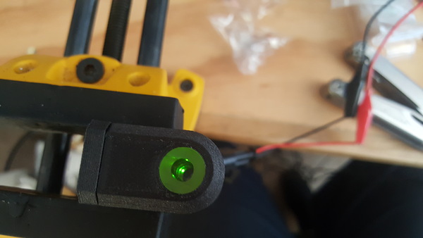
After the silicone dried, I screwed the lid on, and the assembly was complete:
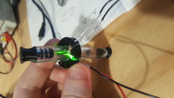
I switched it on and took this picture showing the green light inside the hose, it looks quite cool:
And then I waited for the brass hose barbs to arrive. I could have 3d printed the hose barbs, but I thought that was a bad idea. The natural print orientation to ensure a good seal with the hose would be to have the hose barb standing on end, but this would mean that there is only a very small surface area for layer adhesion between the print layers, and I don't think it would take a lot of force to snap a hose barb 3d printed in this manner. A snapped hose barb in the fuel line would be a pretty catastrophic failure, so I thought it best to use metal ones. I could have made some on the lathe but that's a hassle and off-the-shelf ones are not very expensive anyway.
Calibration
I was originally going to calibrate the sensor by having it write the photoresistor measurement over USB serial and then pick a threshold value that looks to be about halfway between the "with fuel" and "without fuel" values. Unfortunately, the ATtiny85 does not provide USB serial.
I instead made it write the measured sensor reading out using analogWrite() to one of the pins exposed on the programming header, so that I can then measure it with a multimeter. This worked fine, and I found that it measured 1.6v when there was water in the hose, and 2.6v when there was not. The ATtiny85 has a 10-bit ADC, which means 0v become 0 and 5v becomes 1023. Our threshold wants to be halfway between 1.6 and 2.6 volts, so 1024 * 2.1 volts / 5 volts = 430.
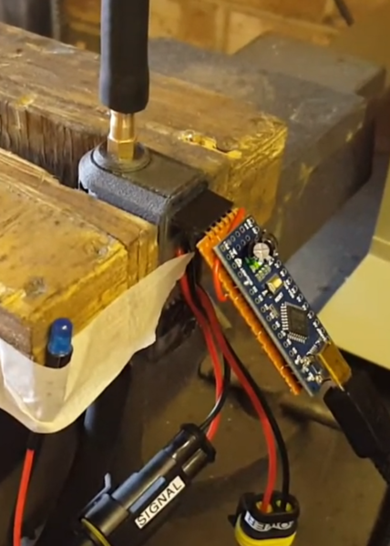
I wired up an Arduino Nano on a piece of copper stripboard with a female 6-pin header on it, to allow convenient programming of the ATtiny85:
Conclusion
Probably I should have been a bit less impatient and ordered some more polyurethane resin instead of making do with the silicone.
Apart from that, I think this looks like a great success. Unfortunately there is not likely to be any lawnmower racing this year due to the coronavirus. Hopefully the 12 hour is back next year and I'll be able to report on whether the device works or not.
I still need to weld a metal bracket in a convenient place on the chassis to cable tie the sensor to, but that shouldn't be a problem. I wanted to build a new fuel tank mount anyway, due to the incident with the fuel tank falling off at last year's race.
If you want to build a FuelSafe device, you should be able to find everything you need in the github repo. I highly recommend the waterproof connectors that I have used. I believe they are a generic no-name product. They are widely available on eBay, at any rate. Please email me if you have any questions or need any help.
Cheers.