
Status on the 3d-printable keyboard switch is that the latest test managed 110,000 presses before failure, on the spinning cam tester.
The switch tester has been a surprisingly popular project, and has been featured on both Hackaday and Hackster. It's just a shame they picked up the servo-based tester instead of the spinning cam! I think my post about the servo-based tester was a bit easier to digest. Less of a stream-of-consciousness.
Switch design
I made the changes described last time, which were:
- remove all unnecessary plastic between the contact wires, to stop it from levering up the contact plate and breaking contact
- redesign the spring housing so it is a bit more suitable (short, and fits in a shelf, instead of tall and wedged into a big square opening)
- use 2 spirals on the spring so that the forces balance and the plunger is pulled to the centre instead of off to one side
- fillet the join between the spiral and its housing
- remove unnecessary height from switch body
- increase clearance around plunger
- make the bottom narrower to accommodate the wires so that it fits in a 14mm hole even with the wires poking out the side
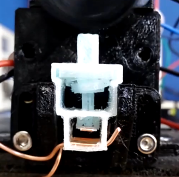
The switch looks like this:
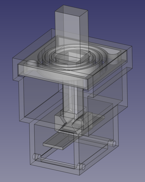
And to make it easier to see, the new spring looks like this:

The spiral is made out of a series of semi-circles because it's easier that way, which is an idea I got from the spiral cuts on the Antikythera Mechanism.
I wonder how easy it would be to use Finite Element Analysis to create an accurate animation of how the spring moves. Or even better, to get an accurate prediction of the switch activation force. I'd probably need to fuse all the parts together at the places where they join, fix the outer case in space, and apply a downwards force on the plunger. It might be a bit harder than that actually due to the preload on the spring (it is stretched out a bit even in the rest position). Might be worth having a go.
Switch testing
I tried to drive the moisture out of my spool of black PETG by baking it in the oven for a few hours, but when I returned to get it out of the oven I was disappointed to find that the temperature had been set to 100°C instead of 50°C. The spool was fused together and unusable. Bummer. Oh, well, I'd been planning to order a spool of clear PETG soon anyway. In the mean time, I have a spool of "PIPG" or "post-industrial PET-G" that I'm not particularly fond of because it tends to block the nozzle. I think "post-industrial" means it is made out of factory floor sweepings. Here's a photograph of what I pulled out of the nozzle one time, taken with a USB microscope:
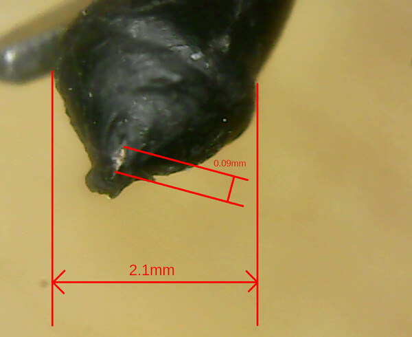
It appears to show a small chunk of brassy-looking metal embedded in the filament, along with a lot of other very fine metallic specks.
I've listed the setup of each of these tests with a small table, with the following fields:
| Material | either the black PIPG or the clear PETG |
|---|---|
| Layer height | height of 3d printed layers (but note 1st layer is 1.5x as tall) |
| Contact plate thickness | thickness of flexible plastic plate that copper tape is stuck to |
| Activation position | amount of keystroke that has to be pressed before the contacts make contact |
Note that the x-axis scale varies each time, so you need to look at the numbers to compare the graphs.
1. PIPG switch, 50% activation, 0.15mm contact plate
| Material | PIPG |
|---|---|
| Layer height | 0.1 mm |
| Contact plate thickness | 0.15 mm (1 layer) |
| Activation position | 50% |
I had previously been using a 0.25mm (2 layer) contact plate, but made a last minute change to 0.15mm because I thought making it more flexible would help. It did not help!
(Although the layer height is 0.1mm, the 1-layer contact plate is 0.15mm thick because the bottom layer is 1.5x the thickness of the other layers. I think this is to aid bed adhesion, I left it alone because it's a default in the printing profile I'm using, but I'm not completely sure I agree with it.)
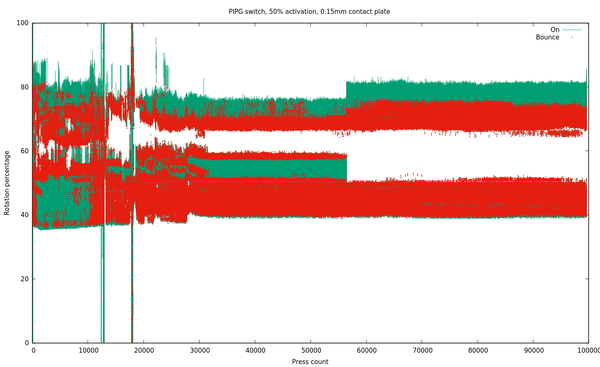
This is absolutely awful. Possibly the worst switch I have yet tested. The contact plate was way too floppy and never made reliable contact. Oh, well. Lesson learned: the contact plate needs some stiffness. The only reason I let it run so long is because I was hoping it would wear in and start working properly.
The charting is basically the same as in the last post: as the motor rotates through 1 full revolution, the y-axis position sweeps from 0% up to 100%. We plot a green line wherever the switch is detected as "on". And this time we also plot a red dot over the top of the green at every point the switch comes on/off apart from the first "on" and last "off" of each revolution. This is a quick and easy visualisation of contact bounce, and also highlights any other discontinuities.
A good result would have a single solid green bar running from left to right with very little deviation up and down, and with minimal red marks.
2. PIPG switch, 50% activation, 0.35mm contact plate
| Material | PIPG |
|---|---|
| Layer height | 0.1 mm |
| Contact plate thickness | 0.35 mm (3 layers) |
| Activation position | 50% |
I re-printed the contact plate now even thicker than before. I actually can't remember if I re-printed the entire switch or just the contact plate. Regardless, I don't think I made any substantial changes apart from the contact plate thickness.
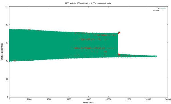
Much more promising. We got almost 11,000 presses before it went bad. There were a handful of "bouncy" presses after ~6,000, but it's not obvious that these would have been a big problem. The keyboard controller will need to have switch debounce logic anyway, so as long as it was just a small bounce and not a large discontinuity, I think it would be fine.
(I was actually surprised to see so little contact bounce. I had assumed that we would see multiple bounces on pretty much every keypress. Perhaps the Arduino just isn't fast enough to notice? Currently the serial port runs at 9600 baud, and there are a few bytes transmitted on every state change. Serial communication blocks other processing, so it's possible that if I increased the serial port speed then I would detect more bounces, but it's inconvenient to change the speed because I'm reading the serial port with "cat" and I'm not good enough at "stty" to make it work at anything other than 9600.)
Once the switch stopped working entirely, I took it out of the tester and inspected it to see what had gone wrong.
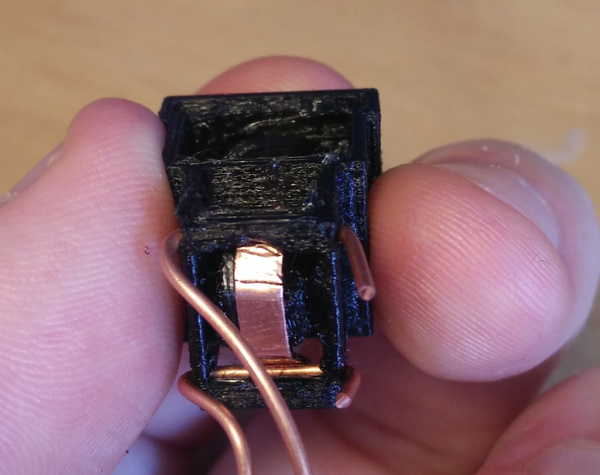
The copper tape has broken! Now this I did not expect. With the constant flexing up and down, we have fatigued the copper to the point that it has failed on us. It makes sense really, but I hadn't expected it because the copper tape felt so flexible.
3. PIPG switch, 75% activation, 0.35mm contact plate
| Material | PIPG |
|---|---|
| Layer height | 0.1 mm |
| Contact plate thickness | 0.35 mm (3 layers) |
| Activation position | 75% |
I spent quite a lot of time trying to work out what to do about the copper tape bending. Ultimately the solution is to find a way to allow the plastic to bend, and provide a spring force against the copper, but keep the copper flat so that it does not wear out. I still haven't accomplished that in a way that is small enough to fit in a switch and simple enough to work reliably, so my "quick fix" was to move the activation position down from the 50% point to the 75% point. That means that at the bottom of the 4mm stroke, the copper tape will only be flexing up by 1mm instead of 2mm, which should prolong its life.
Moving the activation position is a compromise I don't really want to make, and I hope to be able to reverse it eventually, but I had to try it for now anyway.
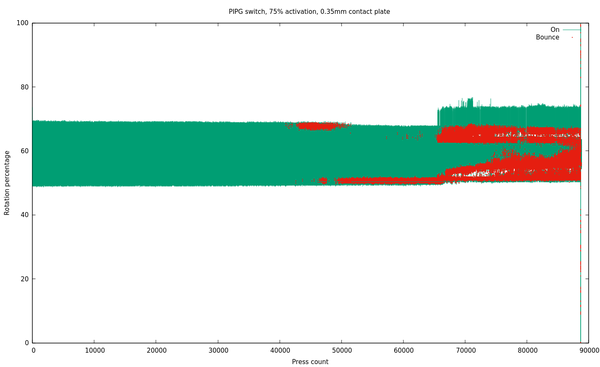
This is much better. We got over 40,000 presses before the switch showed any signs of trouble, and about 65,000 before it became unusably bad. Also note that the variation in activation position is much lower here than in the previous test, presumably due to less stress on the flexible plate. At nearly 90,000 presses it stopped registering entirely. At that point I inspected it to try and see what had happened, and was surprised to find nothing obviously wrong! I prodded and poked at it, and manually tested it a few times, and nothing seemed wrong, so I put it back in the tester to see what would happen.
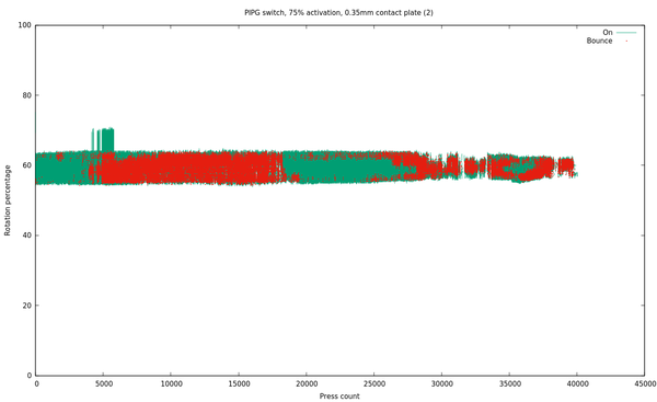
To my surprise, it actually seemed pretty much fine again at first, albeit with a reduced activation range (I probably bent the plate while prodding at it). But it only took 5,000 presses before it started acting strange, so something was obviously not right. Again I eventually switched it off and manually prodded it about, but couldn't find anything wrong so put it back in the tester.
And again it started off looking OK! But this time it only took just over 1,000 presses to break it, and not much more than 2,000 before it stopped registering presses at all. This time I noticed that the copper tape had broken like before. But moving the activation position down seems to have helped a lot: we got between 40,000 and 70,000 good presses before failure, depending on how generously you count them.
4. Clear PETG switch, 75% activation, 0.50mm contact plate
I switched to clear PETG here because this is when the spool of clear PETG arrived. In principle the clear material should be superior because it is not polluted with annoying pigments messing up the mechanical properties of the plastic.
| Material | Clear PETG |
|---|---|
| Layer height | 0.2 mm |
| Contact plate thickness | 0.50 mm (2 layers) |
| Activation position | 75% |
Before printing this switch, I observed that the printing quality I got from my machine at 0.2mm layer height was quite superior to the quality at 0.1mm layer height, so I moved to 0.2mm for this one. I think the difference is that under-/over-extrusion becomes more significant at lower layer heights, whereas with higher layer heights there is more wiggle room. I don't think the change in layer height should affect much. I also increased the thickness of the contact plate so that it would not be just a single layer.
The slight blue tint caught me by surprise. I was printing with some blue PLA right before I loaded the clear PETG into the machine, and obviously there was still some blue material lying around in the hot-end. It's not just a cosmetic problem, either: the presence of PLA mixed in with the PETG will affect the mechanical properties, although I don't know by how much. Worth noting that it can take a long time to fully purge the nozzle between filament changes, though.
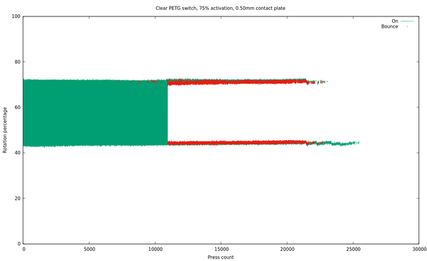
The copper tape broke at about 11,000 presses, which is about the same as we got with the activation position at 50%.
That's quite a disappointing result. I was expecting this switch to perform at least as well as the last PIPG one, because it was basically the same parts but in a different colour. I don't know if I just got lucky with the last switch, or unlucky with this one, or whether the thicker contact plate somehow stresses the copper more, or something else.
I wondered what would happen if instead of replacing the contact plate, I just stuck another layer of copper over the top of the broken one.
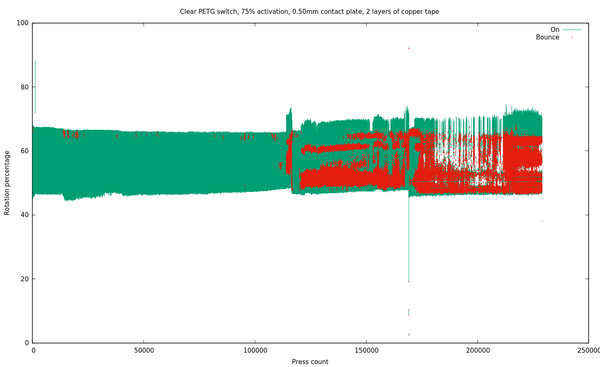
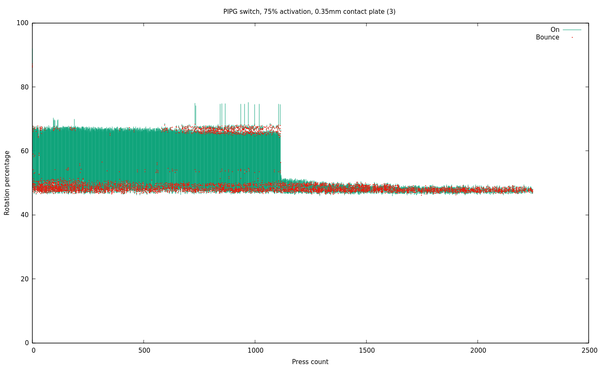
Over 110,000 presses before trouble started! This is the best result so far. Is it just a matter of luck, or is "use 2 layers of copper tape" the magic formula to get more life out of it? More tests required.
(The single outlier near the start is from accidentally leaning on the cam and stalling the motor. The rotation position is determined based on timing, on the assumption that the motor is spinning at a roughly constant speed. Stalling the motor halfway through a rotation throws off the timing for that rotation).
Interestingly, this switch failed the same way the PLA one did: the spring broke. The spring has 2 spirals, and both sides have broken. I expect the trouble that developed around press 110,000 was caused by the spring breaking on one side but still sort-of working on the other. Still, the switch had already been subjected to over 25,000 presses before I put another layer of copper on it, so we know the spring was good for 135,000 presses before it broke. I wonder if the PLA contamination made a material difference here.
I also noticed that the second layer of copper tape has split, but it at least lasted a lot longer before doing so, and in fact the contact plate was still conductive from one side to the other. I tested laying 2 pieces of copper tape on each other with a small overlap, and found that they conducted perfectly well through the adhesive layer, so that gives us a second improvement with 2 layers of tape: not only do we reduce the bend radius of the top (or, bottom) layer of tape, but we also get a second chance at conducting electricity through the switch even if the top layer breaks!
Another design
I did design an alternative switch which uses 2 spiral springs and does not use a flat contact plate. The idea here is that the spiral spring at the top is the main one that you feel when pressing the switch, but when you reach the 50% position, the slotted hole in the plunger engages a thin piece of copper wire and as you keep pressing down, that copper wire is then pushed away from the main copper wire contacts. So this is push-to-break instead of push-to-make, but that's not really important. The wire that bridges the 2 contacts is pressed against them by preload on the bottom spiral spring. In principle it would work but I haven't yet got it quite right. I haven't got enough preload on the lower spring so currently it doesn't make good contact.
Here's a picture of the CAD model, but it's not very easy to understand:
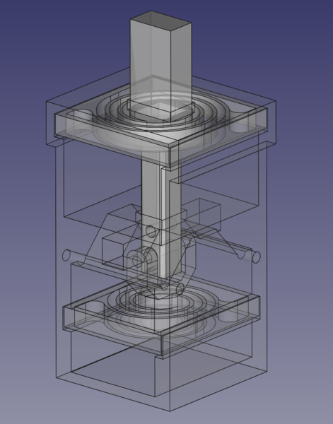
But if just using 2 layers of copper tape is an acceptable solution then I'd much sooner do that, as that switch is easier to assemble and simpler in operation.
Keycaps
I have started experimenting with putting keycaps on the switches. It's the same model I designed before, but with a rectangular hole instead of a Cherry MX cross.
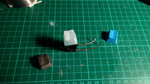
The black one is PIPG, and has been sanded slightly, which didn't go very well. The blue one is PLA, and didn't print very well due to using 0.1mm layer height. The clear one is the clear PETG, and is the best but is still a bit rough.
Arduino library
The Keyboard library for Arduino is very pleasant and easy to use. It abstracts away whatever you might need to know to implement USB HID and just lets you say when you want keys to be pressed and released. Perfect. I'll probably use it for the controller in the actual keyboard. I just wish it would let you set a custom device string to show in lsusb...
With keycaps and software pretty much figured out, and switches looking promising, I am almost ready to make a working macro keypad! If that goes well, I think I'll just need to work out what to do about stabilisers on the spacebar etc., and come up with a sensible way to join 2 halves of the keyboard case, and I can start putting together the actual keyboard.
Next tests
I intend to make a few more of the tester modules so that I can test several switches in parallel, and then I'd like to print a few more switches and get some data with N > 1 on how long they last with 1, 2, and 3 layers of copper tape, 50% and 75% activation position, and possibly various thicknesses of contact plate.