
The day after my first attempt at milling a PCB, my new tooling arrived (a 1 mm drill bit and a 10° engraving tool), so I had another go at making a PCB.
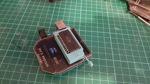
Here's what I made:
(More pictures of the process available.)
And here's a video of it all:
The big problem last time was that the cut depth was too inconsistent, and my plans for fixing that were to re-surface the wasteboard so that the PCB is more square to the machine, and to use mesh leveling to counteract any remaining unevenness.
I re-surfaced a portion of the wasteboard but didn't bother with mesh leveling, and this turned out to be good enough. Great success.
Isolation routing
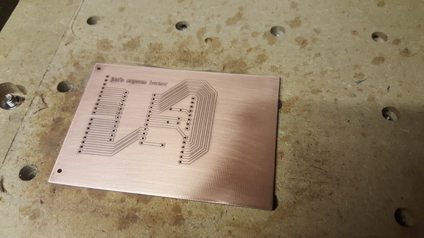
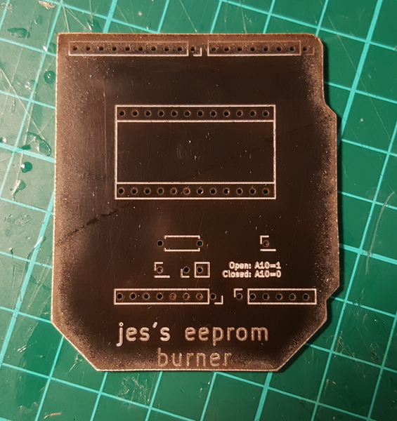
After the isolation routing, the board looked like this:
You might be able to see that the routed traces have quite a rough edge. Maybe this would be improved by cutting more slowly. I fixed it by sanding with some quite fine sandpaper:
This might have left some copper dust in the gaps between the traces. I'm not sure if there's a better option here. I cleaned up the gaps by running a sharp knife through them to extract the dust.
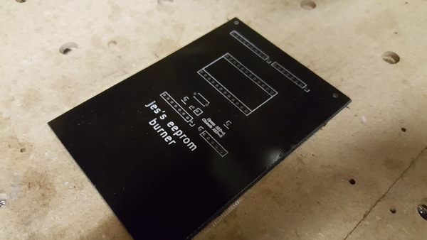
Silkscreen
I did the silkscreen by first spraying the non-coppered side of the board black, and then engraving the silkscreen layer into it. This worked really well, I would do this again.
Edge cuts
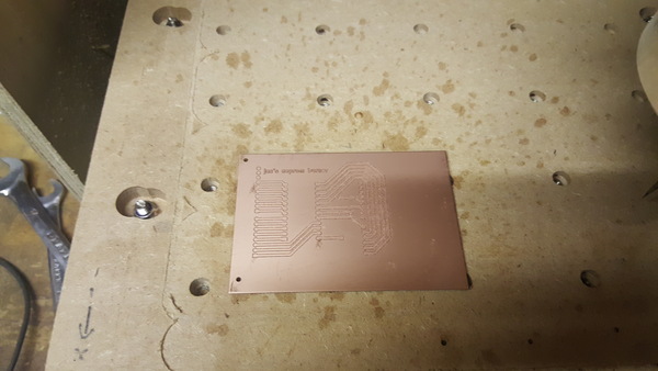
I made a bit of a mess of the edge cuts:
There was a lot of tearing and burning as it was cutting.
I initially thought that this was caused by running the cut too fast for the 2 mm end mill, but I subsequently discovered that the collet was loose! I'm surprised it managed to cut at all and didn't just break the end mill.
I cleaned up the edges of the board with a file, and tried to clean the mess off the paint with soap and water, but it was to little avail. Next time I should tighten the collet instead.
Soldering
The soldering was very tricky, due to the lack of soldermask.
There is only a very small amount of clearance between the pads and the rest of the board. I managed to create a couple of solder bridges, which were tricky to clean up.
Re-melting the solder that has jumped the gap is not a successful strategy, because the more you heat it up, the more it wants to flow onto the copper. I eventually found that cutting through it with a sharp knife works better.
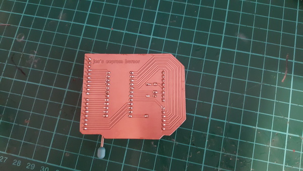
See the pin nearest to the camera:
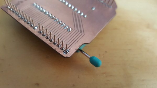
Another issue is that because there is only copper on the bottom side of the board, and I want the pins to stick out the bottom, I couldn't solder the pin header on "correctly". I bodged this by sliding the plastic clip right to the end of the pins, putting the clip on the top side, and soldering the pins on the copper side. It does the job, and I can't really think of a better solution on a single-sided board.
Writing to an EEPROM
So far I think the homemade PCB is a great success. Apart from the burnt edges it is all very high quality, much better than I expected.
Now there's just the small matter of actually using the EEPROM burner.
To cut a long story short, I couldn't get it to work.
I have tentatively concluded that the EEPROM chips I've bought just don't work. I couldn't get them to do anything at all. To rule out my homebrew PCB, I plugged an EEPROM chip into a breadboard, applied power, enabled "chip enable" and "output enable" by tying them to ground, disabled "write enable" by tying it to 5 volts, and found that all of the output pins were still floating. The relevant section from the datasheet is:
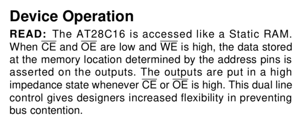
Which seems pretty unequivocal. Even though I left the address lines floating, there should be at least some value asserted on the outputs, but there is nothing. Frustrating. I don't know if the chips are real AT28C16's that are just broken, or if they're some random other less valuable chips that have been rebadged and flogged off on eBay. Either way they're not much use to me.
The chips were packaged extremely poorly when they were sent to me:
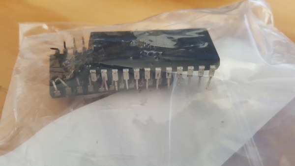
I wonder if this is because the seller knew they didn't work and therefore didn't want to waste any money on unnecessary packaging materials.
I initially bought 2 packages of 2 chips each from this seller, because I need 4 in total, and they arrived on separate days. After the first package arrived, I messaged the seller to complain about the quality of the packaging, and was told that this isn't intended and must be a one-off mistake. When the second package arrived, it was packaged identically to the first, and also had bent pins. I left negative feedback and moved on, but even at that point I didn't expect that the chips just wouldn't work!
Fool me once, shame on you. You can't get fooled again. So I have this time ordered only a single AT28C16, from a different seller, and look forward to testing it.
Backplane
Since making the EEPROM burner, I had a first attempt at making the backplane for SCAMP, but I chipped the end off the engraving tool by running the cut too fast (due to a software bug). I have some more engraving tools on the way, and will hopefully blog about my completed backplane soon.