
All of the SCAMP hardware is now mounted properly inside the case, with no Arduino or breadboard required. I'm now well into the "long tail" of tasks on this project, where it takes increasingly large amounts of time to produce increasingly small improvements.
I think I'm almost ready to bolt the box together and not open it again. I just need some way to transfer files between the SCAMP and my Linux PC, which would be either a removable CompactFlash card or a secondary serial port. There is already some hardware provision for both of these, so it might just be as simple as plugging a second 8250 into the serial card and connecting up the pins on its front panel.
Here are some pictures of the computer:
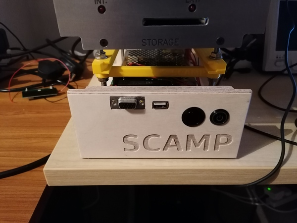
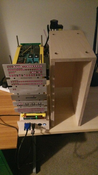
All of the electronics are mounted to the base, with a small panel at the back holding the power socket and at the front holding the power/reset buttons and VGA console. Then the wooden box can drop over the card cage and bolt down to it. The wooden parts are made of 15mm "Russian birch" plywood. I believe this is sold as "Baltic birch" in other parts of the world. It's great quality stuff, I like using it.
I'm quite pleased with the joints on the box:
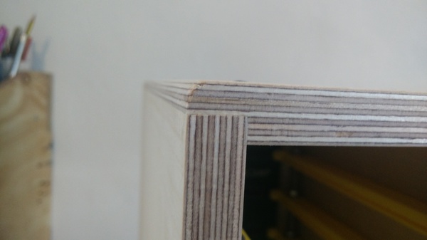
I made all of these parts on the CNC machine, with a deliberate slight overhang on the joints, and then planed them flush by hand after gluing.
And here's a short video showing the current state:
(In the video the serial port output doesn't work at first, and I suggest that the VGA console might not have been ready. But on further reflection this can't be it, because the VGA console is already drawing a cursor. The output actually starts working after the point that the kernel re-initialises the UART, which suggests that when the bootloader tried to initialise the UART it didn't work. I don't know why that would happen. Possible problems ahead...)
Front panel
I was originally planning to put the clock and power/reset buttons on a dedicated card plugged into the backplane, but given that I only have 2 spare slots, I decided I'd rather not waste one. So power and reset buttons are on a panel mounted to the case, and the clock is super-glued to the backplane.
It might have been nice if I'd got 2 buttons that were both the same size.
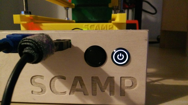
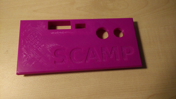
I really like the effect of the power button lighting up when it's switched on. I'm also quite fond of the text engraving. I did this with a 2mm single-flute down-cutting end mill
The VGA console is attached to the back of the front panel with a 3d-printed bracket. It is extremely close to the power supply. You may not believe it from the photograph, but it actually doesn't touch - but it can do if you press on the front panel, so I have prevented it from shorting out by sticking some insulating tape to the power supply.
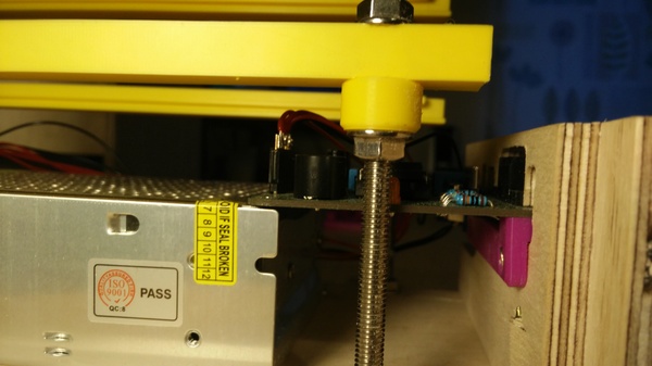
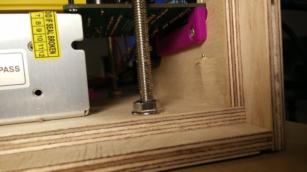
You can see I have very skilfully managed to stick the mounting screw out the back of the panel. Well, at least I didn't stick it out the front! The rest of the case is only held together with glued joints, but I decided to screw this one because I might need to take it off to gain better access to the stuff mounted on the back.
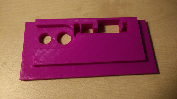
Because there's not a lot of room in this part of the case for the VGA console PCB, I went through a handful of 3d-printed iterations of the panel before cutting it out on the CNC machine.
Clock
Don't laugh: the clock is mounted to the backplane upside-down with super glue.
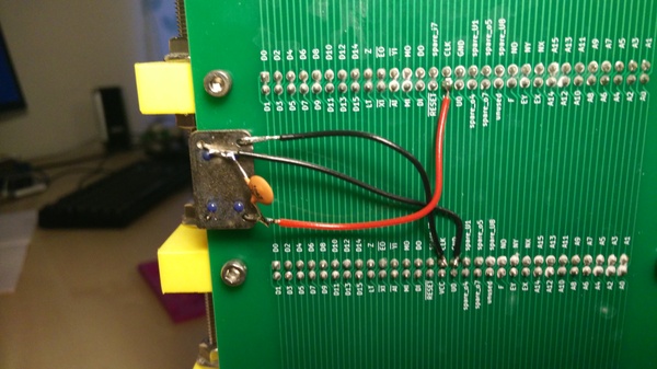
This is kind of hacky but it'll do for now. If it doesn't cause any problems then it'll probably stay like this permanently. I think the most likely problem is that I'll bash it while trying to drop the case on, and short one of the pins.
It is just a 1 MHz crystal oscillator. It seems like a great invention, I wonder why anyone ever uses a bare crystal.
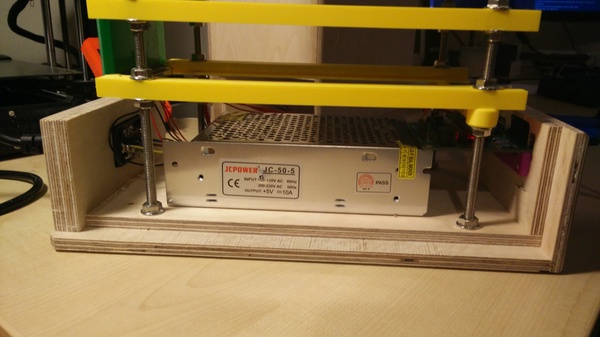
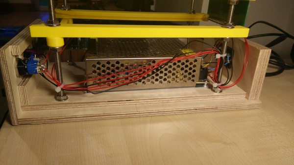
Power supply
The power-supply is screwed to the bottom panel of the wooden case:
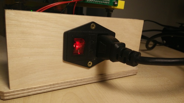
The AC power socket in the back has an integrated switch and fuse. Unfortunately the fuse holder is an unusual size and I couldn't find a fuse that would fit, and since UK power plugs have integrated fuses anyway, I decided it was fine (arguably best) to bypass the fuse in the power socket.
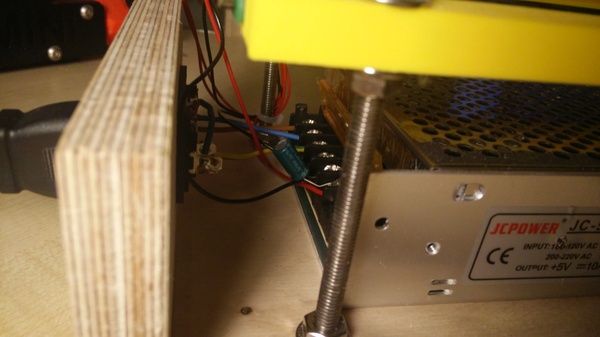
I'm not sure if the capacitor across the 5v output is doing any good. I don't expect it is doing any harm.
Wiring
We need to run a few wires from the backplane out to the front panel. Namely:
- Power & ground
- Reset
- TX & RX of serial console
It's reasonably tidy, and running all the wires down one side means I have plenty of room to work on it if I unscrew the front panel and cut off the cable ties - I can then bring the whole panel around to the side of the machine with a good amount of slack in the wires.
CompactFlash
I previously thought my original CompactFlash interface was going to be adequate, but after wiring up the new front panel, mounting the power supply inside the case, and moving the clock source to the middle of the backplane, it didn't work any more. Bummer. I'm not sure if it didn't like the new clock placement, or didn't like being so close to the power supply, or something else. Don't know. This is kind of the "dark magic" side of electronics for me.
So I made a 2nd revision of the CompactFlash interface, this time putting 74HC245 "bus transceivers" on the data lines between the card and the bus, as recommended by PickledDog.
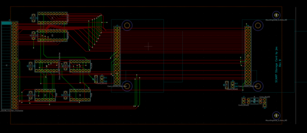
It seems to be an improvement, in the sense that it now works with both of my CF cards where the previous one only ever worked with one, and it now works up to 1.2 MHz (although there is other instability at that speed).
But it didn't magically make the computer start working on its own, so there is obviously something else about the CompactFlash interface that is a bit sensitive. I found that moving it to the middle of the bus made a big improvement. I don't really know why. I wish I understood this stuff better. My mental model is that a conductor is at either 0v or 5v, and voltage changes propagate infinite distance instantaneously. It's frustrating that this is not a sufficient model for even my puny computer at my puny clock speed.
Other
SCAMP has been accepted into the Homebrew CPU ring. I think I'm expected to put the webring home/previous/next/random buttons on the project page, but since the project page is currently just a README.md on github, I've settled for adding a link to the Homebrew CPU ring in the "Resources" section.
I've been reading Starting FORTH, a FORTH tutorial from I think 1981. You can read the PDF online. FORTH is a fascinating language, but I still don't think I'm completely sold. FORTH code quickly gets completely unintelligible if you don't break it down into a large number of small "words", but the requirement to find a word to describe each part means you end up with lots of words that all sound the same but do slightly different things. I also found it to be slightly inconsistent with the Reverse Polish Notation. For example, : lets you define a new word, but it has to come before the word you're defining, because it operates on the input stream rather than the stack. But all words can do that: any word can take its argument from the input stream instead of the stack. You just have to develop a mental model in which it is clear where the arguments for any given word are going to come from, but I'm not there yet.
I read that to truly understand FORTH you need to implement your own, and implementing FORTH sounds like a much more compelling proposition than actually writing programs in it. So I think it's fairly likely I'll be making a FORTH system for SCAMP, and from there it's fairly likely that the edit-compile-test loop in FORTH will be substantially faster than in SLANG, so if I get on with it I may end up using FORTH for some of Advent of Code, which might be fun.