
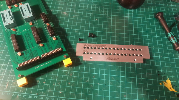
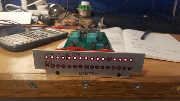
I've put together the memory card for the SCAMP CPU, including the front panel with LEDs to show the bus contents and address register.
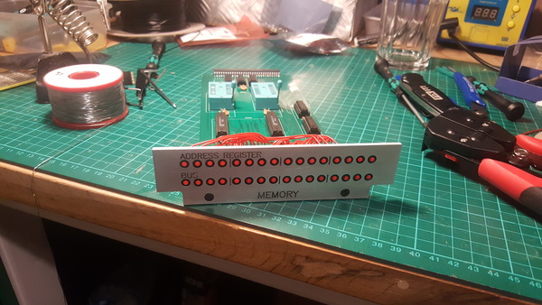
The SCAMP CPU won't have a "normal" front panel, where all the switches and lights are on a single panel at the front of the case. Instead, each card will have its own panel, all visible at the front of the case.
Design
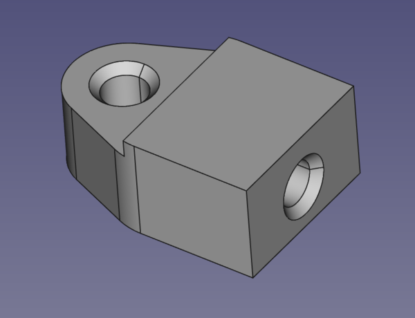
The first problem to solve is how to connect the panel to the card. I settled on 3d printing some brackets to take 2 brass threaded inserts. One would be used to screw the card to the bracket, and the other to screw the panel to the bracket:
I expect that the cards might be quite hard to pull out of the backplane, because the insertion force on a 60-pin connector is considerable. For that reason, I wanted the front panels to be quite robust. I don't want to bend them trying to unplug the cards. So I wanted to make the panels out of a 3mm plate. But my panel-mount LED holders call for a ~1mm panel:
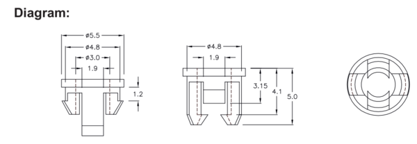
I made a few 3d printed test pieces and determined that they would actually fit nice and tightly in a 2mm panel, but that's still not as thick as I would prefer, so my solution was to make 1.2mm deep stepped holes for the LED holders:
That way we get the stiffness of a 3mm panel while presenting a 1.8mm interface to the LED holders. Arguably this is even neater than the recommended installation, because it means the LED holders end up roughly flush with the panel surface instead of sticking out.
With the mounting problems solved, it's just a case of modelling the part. I used FreeCAD as usual, and all of the CAD files are in the front-panels/ directory in the git repo.
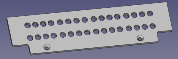
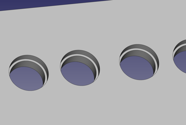
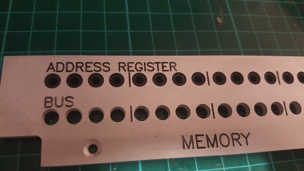
You might notice that the holes are not quite equally-spaced. They're grouped into 4s to facilitate reading out hex.
The reason for the cut-out corner at the bottom on each side is that I plan to use that space to insert a lever tool of some sort to help unplug the card. Or at minimum, to insert fingers. Again this is because I expect the cards to be quite hard to unplug, and I want to make it as convenient as possible.
I've always found FreeCAD's text handling facilities are more trouble than they're worth, so I laid out the engraving in Inkscape instead:
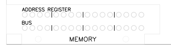
The bulk of the work here was laying out a faithful reproduction of the outer profile and hole locations, to make sure it all lines up properly. (Foreshadowing).
I used the Hershey Text Inkscape plugin to create the text, and "Path to Gcode" from the gcodetools plugin to turn it into G-code. This is a workflow I first learnt for engraving the text on Emma's spinner pendants.
Protip: you can cat multiple G-code files together and open the result in FreeCAD to ensure that everything looks like it is going to work together in the same coordinate system:
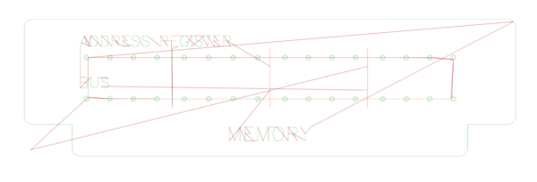
(Another protip: turn off the background colours in FreeCAD to look at G-code paths, because green on blue is hard to see).
Cutting
I thought about making the panels out of brass because it's more classy, but I already had a 3mm aluminium plate, so I used that instead.
I initially tried to cut it out using 2mm cutting tools, and had a very bad time. I kept breaking the tool, and do not completely know why. After breaking the first couple of tools I tried to calculate correct feeds and speeds, but they were way faster than seems reasonable. I tried it anyway, and the tool broke almost immediately.
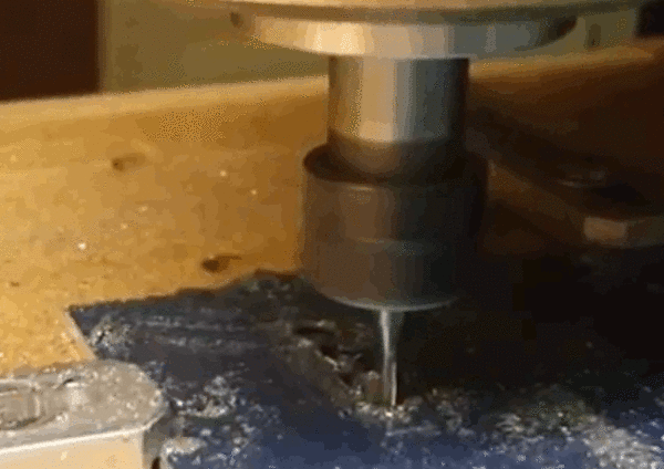
Having exhausted my supply of 2mm tools, I regenerated the G-code to use a 4mm tool, with some apprehension because I was not convinced my router is powerful enough to push a 4mm tool through aluminium.
To my surprise, it worked perfectly on the first try. Incredible. I'll be using larger tools more often. They are more robust, and despite having to remove more material, they also cut faster.
The 4mm tool is too large for the countersunk screw holes, so I spot-drilled those on the CNC machine and finished them by hand.
Finishing
To tidy up the worst of the burrs on the engraving, I left the part in sodium hydroxide (aka caustic soda) for about 10 minutes. In addition to dissolving the burrs, this leaves a nice surface finish similar to sand-blasting.
To make the writing stand out better, I dripped a bit of paint into it and then rubbed off the excess with isopropyl alcohol. I haven't done a fantastic job of this, I will try to do it better next time.
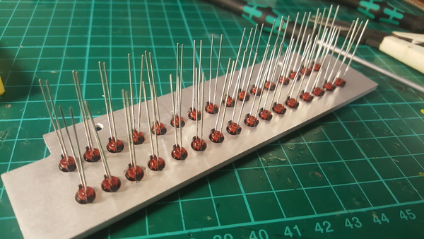
Then put the LED holders in.

Push in the LEDs.
Trim the leads and solder all the negative legs together.
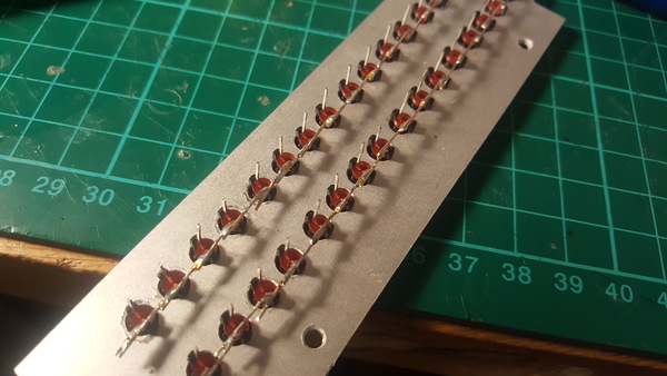
And solder the wires on.
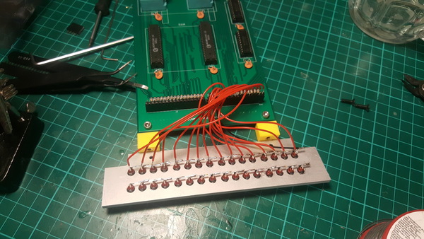
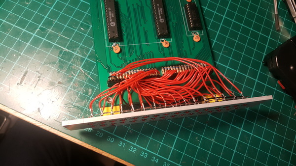
I found that soldering the wires for the LEDs was extremely boring and time-consuming. I still have more than 80 left to do on the other cards (X register, Y register, ALU output, instruction register, microinstruction), which I am not looking forward to.
I also found that one of the LEDs doesn't work, that's annoying:
I will have to replace it.
I also noticed that the vertical lines in between the groups of LEDs aren't centred! I don't know how I managed this. What a blunder. I should have checked the G-code more carefully. I'm not going to make it again though, I'll just live with it.
Case
I have done a little bit of thinking about the case. I think it might be nice to make it out of wood, with aluminium guide rails inside for the cards to slide on. I need the case to hold the backplane at the back, hold guide rails at the sides, hold a power supply probably somewhere at the bottom, and protect the cards. I accept that wood is not a very technical material, and perhaps not befitting of a CPU, but I think it would end up neater than anything I could come up with by trying to bend sheet metal. And it might be nice.