
I have managed to make the toolmaker's clamp that I mentioned last time. It is made out of mild steel, which is soft for a machinist's tool, but harder than wood, plastic, and aluminium, which are what I'm normally limited to. Since I made it, it belongs to me, and a clamp is a type of tool, I suppose this is both a toolmaker's clamp and a clampmaker's tool.
It can be used for holding small parts while drilling, filing, tapping, etc., or for transferring multiple parts between more substantial workholding arrangements (e.g. the vice on the mill and the vice on the bench) while maintaining their alignment, and probably for lots of other things.
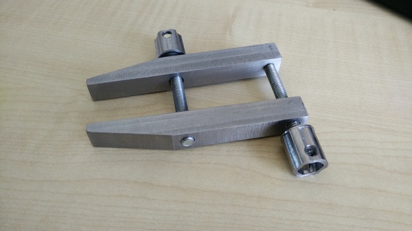
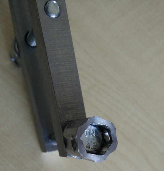
The way it works is you tighten up the front bolt (which pulls the jaws together) until the clamp is grabbing the work, and then tighten up the rear bolt (which pushes the jaws apart, it has a small section at the end of the thread turned down to locate in a matching hole) to lever the clamp against the front bolt and increase the clamping pressure. The knobs have holes in so that an allen key or similar can be used to provide more torque to the bolts.
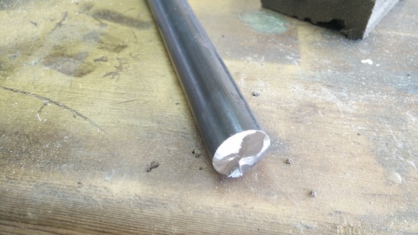
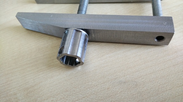
I made it out of hot-rolled mild steel bar stock, because it was the most convenient material I had available, so apart from the 2 bolts, this is what it all looked like before I started:
Knobs
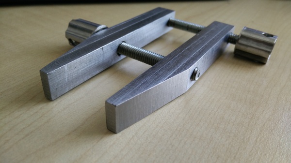
Normally on a toolmaker's clamp the knob and the screw thread would be made out of a single piece of material, with the knobs knurled on the lathe. I don't have a knurling tool and have always found cutting long threads in thin material to be quite tricky, so I decided to make life easy for myself and use existing M6 bolts, with the knobs machined separately and pressed on to the heads.
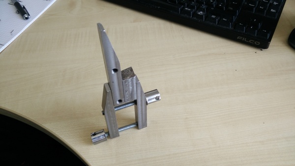
This turned out to be a bad idea, because the knobs ended up wider than the clamp jaws. This means, for example, it's not possible to use my clamp to hold something perpendicular to the pillar drill table for drilling, because the knobs prevent the jaws from sitting flat. Fortunately it won't be any harder to remake the screws now than it would have been to make them in the first place, so I can always replace the screws if it bothers me.
The jaws are 12mm across, and the head on the M6 bolts is 10mm across. This sketch in SolveSpace shows that a 10mm hexagon is 11.55mm across at the widest point:
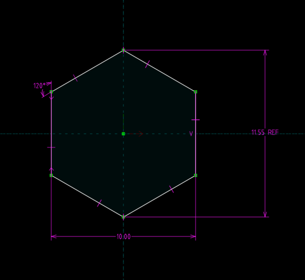
So if you want the knob to press onto a 10mm hex head, and you want it less than 12mm in diameter, then you'll have less than 0.25mm wall thickness, which seems not enough.
I made the knobs with a 5mm end mill, whereas I made the jaws of the clamp with a 10mm end mill. I found that the 5mm end mill gives a much superior surface finish. I'm not sure whether the 5mm tool is made better, or whether my feeds and speeds were better. I used Bryan Turner's feeds and speeds calculator for both tools. Maybe it is just down to the rigidity of the machine.
Flood coolant
I haven't got around to improving the drain on my tub yet, but I ran some of these jobs with flood coolant turned on, and it worked really well. It did a great job of keeping everything cool and blowing chips away from the work. Since I haven't fixed the drain, I did end up submerging one of the stepper motor connectors, and nothing bad happened, so it looks like the coolant is indeed non-conductive. I also haven't noticed any rust developing, so that's good too.
Here's a video of the finishing pass on one of the jaws:
I don't know why it makes a horrible noise when cutting in the Y axis but not in the X axis. It should have been taking the same width of cut on all sides of the part.
Draughting
I've been getting interested in hand draughting lately, so I did a drawing of the toolmaker's clamp jaws while I was halfway through making them. I'm not sure how legit it is to have one drawing specify 2 slightly different parts, but I decided it beats having to draw it twice.
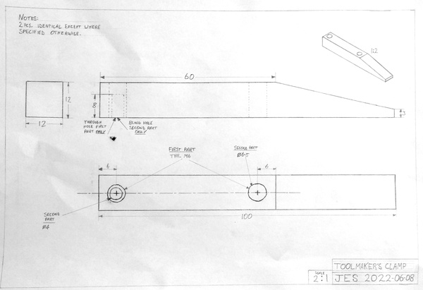
The jaws I made don't exactly match the drawing, but they're quite close. They're about 96mm long instead of 100mm because of a small blunder (I forgot to account for the diameter of the tool when zeroing my coordinates, rookie mistake). And the supposed 8mm deep blind hole is actually a through hole, because of another small blunder: I started drilling the hole from the wrong side, and a blind hole from the wrong side doesn't work, so it had to become a through hole.
At this point I didn't have a sensible way of drawing circles, so the circles are drawn freehand. I think it's OK apart from the circles.
Here's a poorly-lit photograph showing my homemade draughting equipment:
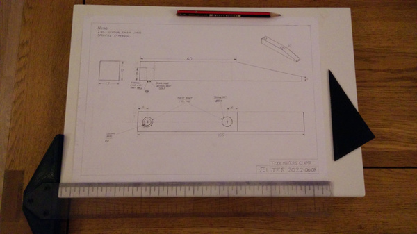
The board is an offcut of kitchen cabinet material (MDF with a very smooth paint job). The 30° triangle is 3D-printed, and is only there to assist with the isometric view. The T-square has a 3d-printed board edge follower on the left hand side, and the transparent plastic ruler is made out of a piece of broken perspex from a picture frame. The markings are engraved with a drag engraver on the CNC router and then coloured in with Sharpie to make them black.
It felt a bit absurd to draw a 30° angle in CAD in order to 3d print a triangle to allow me to draw 30° angles on paper, but it was genuinely the quickest way I could think of to create a 30° triangle.
Since then I have also made a simple compass, so I might be able to draw better circles next time:
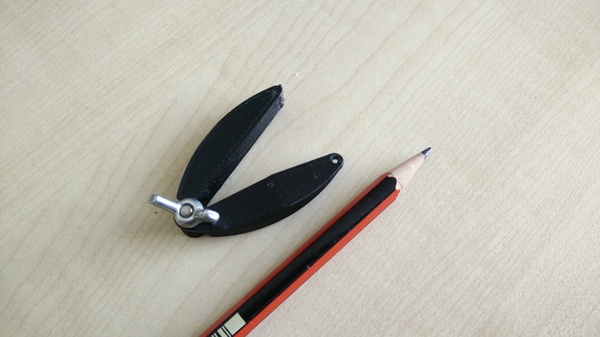
On the underside there is a pin from a pogo pin pressed in with a soldering iron to provide a sharp point. You just adjust the radius with the wing nut, push the point against the paper, put the pencil in the hole, and swing it in a circle. I haven't used it in anger yet, so time will tell whether this is easier or harder to use than a normal compass. It's based on John Heisz's compact compass design.
And I have some vague plans for an ellipse-drawing tool to help me draw circles in the isometric view. There is prior art for ellipse-drawing tools, but I'm not aware of one that maintains the aspect ratio as you adjust the size. The ones I've seen have 2 adjustments that you have to adjust together to get the ellipse shape you want, but for circles in isometric view, you always want the same aspect ratio. So maybe I can invent a new thing here. Or more likely it already exists and I just haven't found it yet.