
I've been playing with my weird rotary axis for a couple of weeks now. It's a rotary axis mounted on the gantry, with the rotation of the chuck geared off a toothed rack on the table. I've had a few questions about the practicalities of using it, so this is some of what I've learnt.
The short answer is that it works a lot better than I expected, and there is a fun trick to creating toolpaths with normal 3-axis CAM software. If you are tempted to build one of these, you should do it. The only expensive part is the chuck. You can either borrow the chuck from a nearby mini lathe, or failing that you can screw workpieces directly onto the plywood gear, or 3d print some sort of fixture. You'll want to keep the cutting forces low anyway, so the workholding doesn't need to be anything clever.
Principles
There are a few key things you need to know in order to do the calculations to control the rotary axis. The first one is the pitch circle of the gear. For metric gears, the diameter of the pitch circle is defined to be the tooth module multiplied by the number of teeth. The circumference of the pitch circle is the diameter multipled by pi. If you move the Y axis through a distance equal to the circumference C of the pitch circle then your gear will perform 1 complete revolution.
Distance for 1 revolution, C = π * module * no. of teeth
In my case, the tooth module is 3 mm and there are 30 teeth, so for me C = π*3*30 = ~282.74 mm.
If you want to move through an angle of α°, then you can scale the circumference accordingly. For example, to move through 90°, you need to move through a quarter of a revolution, because 90 is a quarter of 360.
Distance for rotation of α° = C * α / 360
Sometimes it's more useful to work with distances than angles. For example, if your part has a circumference of Cpart and you want to cut a line of 5 mm on it, how far do you need to move the Y axis? Just multiply 5 by the ratio of the rotary axis's pitch circle circumference to the part's circumference:
Distance on the Y axis = distance on the part * C / Cpart
Let's define the ratio R = C / Cpart. So if our part is 20 mm in diameter, then it has a circumference of 20π = ~62.83 mm, so R = 282.74 / 62.83 = ~4.50.
So to cut a 5 mm line around its circumference we need to move the Y axis by 5*R = 5*4.50 = ~22.5 mm.
Feed rates need to be scaled by the same ratio as distances, because we care about the feed rate at the surface of the work piece, not at the surface of the table. If we want to feed the tool into our 20 mm part at 1000 mm/min, then we need to command the machine to move the Y axis at 1000*R = 1000*4.50 = 4500 mm/min.
Calculating the feed rate gets more complicated for diagonal moves, because distances and feed rates in the X axis are unaffected by the rotation. You can calculate feed rates for diagonal moves by working out the ratio of the length of the movement on the table to the length of the actual cut on the work piece (using Pythagoras to work out the distances - form a triangle with X distance on one side and Y distance on the other, and the hypotenuse is the total distance of the movement). Multiply your desired feed rate by this ratio. (But if you find yourself having to do this calculation more than once then you should probably try to find a better way to make your toolpaths).
3-axis CAM
There is a fun trick for making toolpaths for the rotary axis:
- model the part as a flat "unwrapped" equivalent
- generate the toolpaths to cut out the flat version
- reconfigure Grbl's Y axis using the R ratio calculated above
- the toolpath is magically wrapped up onto your cylindrical part
I modelled this ring in FreeCAD as a flat part:
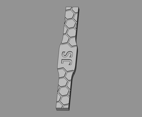
I want the outer diameter of the ring to be 26 mm, so the outer circumference is π * 26 = ~81.68 mm. I modelled the ring as a flat part that is 81.68 mm long in the Y axis, and generated suitable toolpaths to cut the ring out of a flat piece on the table.
For Cpart = 81.68 mm, on my machine, R = 282.74 / 81.68 = ~3.46. Then we just need to update the Y axis settings as follows:
| Setting | Linear | Rotary |
|---|---|---|
| $3 (axis invert) | 7 | 5 |
| $101 (Y steps/mm) | 320 | 320 * 3.46 = 1107.2 |
| $111 (Y max. velocity, mm/min) | 4000 | 4000 / 3.46 = ~1150 |
| $121 (Y max. acceleration, mm/sec2) | 50 | 50 / 3.46 = ~13 |
The most important setting is $101. This should be set precisely otherwise your toolpaths won't line up properly with rotations of the chuck. $111 and $121 only need to be set approximately. These are limits to how fast the machine can move around, so they need to be divided by R to cancel out the multiplication in $101, otherwise Grbl will try to move the machine too fast, because what Grbl thinks is 100 mm (i.e. what is 100 mm on the work piece) is actually 346 mm in physical space.
And don't forget to toggle the Y bit in $3, because in rotary mode the top of the part is effectively moving in the opposite direction relative to the tool.
Also don't forget to put these numbers back when you're done otherwise all your non-rotary parts will be mirrored and stretched in the Y axis!
There are a few really good reasons to do the rotary axis CAM this way:
- a lot more tooling is available for flat 3-axis CAM than rotary CAM.
- it will never try to do more than 1 complete rotation, so you'll never drive past the end of the toothed rack, which is a limitation that most rotary CAM isn't likely to be aware of.
- feed rates are scaled automatically, so you don't need to worry about setting your feed rates correctly for X vs Y movements, and in particular you don't need to do any calculations for diagonal moves, and you even get correct arc movements for free.
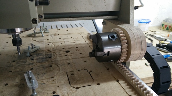
"Tailstock" support
I 3d-printed a wheel to support the loose end of a long aluminium cylinder. It is all held tight by a threaded bar that runs through the middle of the work piece, chuck, and bearings, secured with a nut at both ends.
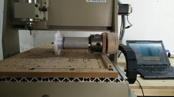
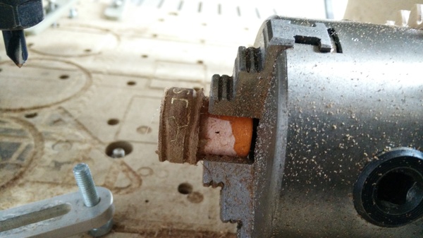
This is OK but not amazing. It stops the part from being ripped out of the chuck in plunge cuts, so it does its job in that sense. But it does nothing at all in the horizontal plane, so you still get more flex at the end furthest from the chuck. Also, the wheel is slightly larger than the pitch circle of the rotary axis, which means it wants to roll further for the same angle of rotation. This means the wheel is constantly slipping against the table.
To stop the wheel from slipping we could make the wheel the same size as the pitch circle of the gear, and put a raised "road" on the table for the wheel to roll on. A further improvement would be to replace the wheel and road with another gear and rack, and this would get us some lateral stability as well. If I do much more work with long parts I will probably give this a go.
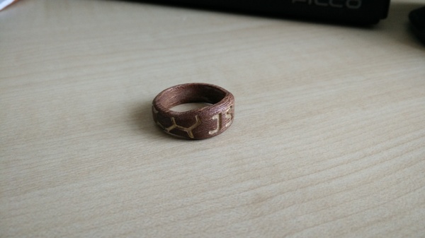
Rings
I made the wooden ring for myself, and put my initials on it. This was made by hot-gluing a "blank" (cut out with the CNC machine in its normal linear configuration) to a 3d-printed mandrel held in the chuck:
The letters and hexagons are cut first, then painted gold, and then the surface is machined down to expose the wood underneath, leaving the gold paint only in the valleys. Here's a video showing the engraving (sorry about the audio, I don't know what happened):
I made this ring to wear at a wedding I attended at the weekend. Since getting married and getting used to wearing a ring every day, I have really got into wearing rings at special occasions. So far 4 people have told me I should try to sell these rings, and 2 people have told me I shouldn't, so to test the water I have made an initial batch of 5.
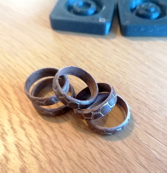
I made the batch of 5 in largely the same way as the first one, except with a larger mandrel so I can mount 5 blanks at a time, and I didn't engrave my initials on them because most people have different initials. They're available in my etsy shop.
If I were to make more rings I would do them differently. I think these are weaker than they need to be because the grain runs across the ring in the long direction instead of the short direction. They should have the grain running along the direction of the finger, rather than perpendicular to the finger. Also, instead of making each of the ring blanks individually and then measuring their coordinate offsets and machining patterns on them individually, I would start with a single long tube of wood, with the grain running axially. I'd machine the pattern over the entire surface of the tube without regard for where each ring is going to start and finish, and then I'd part off individual rings from this large tube. I think this would be a lot less work.
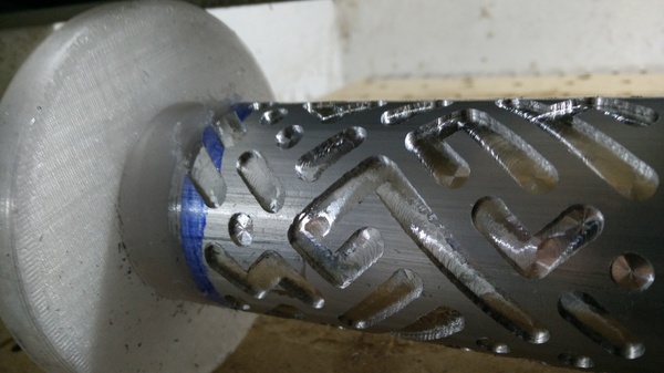
Cylinder Puzzles
I've designed a puzzle that involves shuffling rods back and forth through a cylinder, to allow the inner "puck" to be removed. It's a type of maze puzzle where you can see all the parts of the maze, but it's still difficult to find the solution because the possible movements are so hard to see.
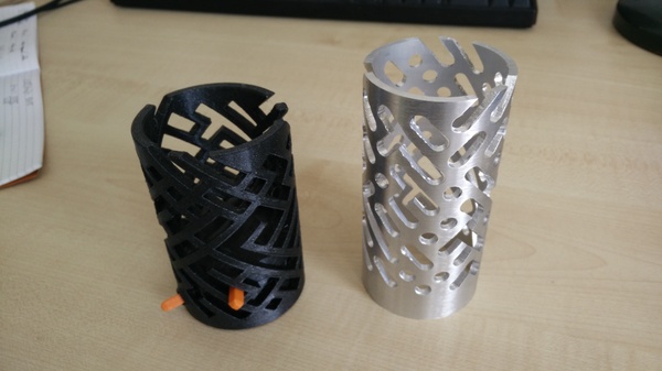
The one on the left is 3d printed and the one on the right is machined out of aluminium. The machining is not great, and the part is worse at the end that was further from the chuck, because my "tailstock" support wheel doesn't provide a lot of support, but it's a very promising start. I still need to make metal versions of the puck and the sliding rods.
For this part I did not use the 3-axis CAM trick. I'm using a similar ASCII-maze-based workflow for this puzzle as I am for Party Puzzling, so I wrote a Perl script to turn the ASCII art maze into G-code.
I started by testing out the machine and the toolpaths on a random piece of plastic pipe:
It worked, but the (PVC?) plastic pipe does not machine very well at all! It makes a real mess. I eventually worked up the courage to try it on aluminium:
I broke the endmill on the first attempt because I was trying to use feeds and speeds borrowed from the web. It seems that for cutting aluminium with a router you need to use much higher RPM than real machinists would use. I don't know why. From first principles I think there should be an optimal relationship between RPM and feed rate, so that you're taking a proper chip and not rubbing the tool against the work, but it seems that on a router it cuts a lot better (and doesn't break the tool!) if you take much smaller nibbles than what machinists will tell you to use.
I don't know, maybe I just don't understand.
I found that running the spindle at 8000 rpm and feeding at 800 mm/min worked best. It's a 6mm 2-flute carbide end mill.