I've made some aluminium keycaps on the CNC machine. I couldn't work out how to do the CAM in FreeCAD (although I think I have now roughly figured it out), so I instead wrote a program to render depth maps of STL files so that I could generate toolpaths with my pngcam program (github).
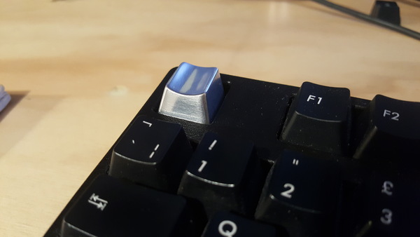
Here's what a finished keycap looks like, installed on the keyboard:
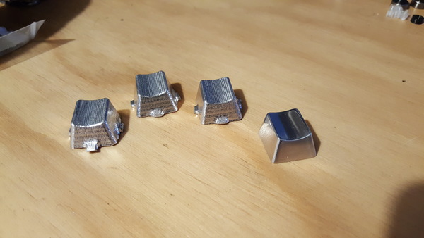
I actually made 4 of these, because Ben told me people might buy them if I listed them on Etsy, although I have only taken the time to sand and polish 1 and now can't be bothered listing on Etsy. But if you happen to want to buy one for £20 (plus postage if you live far away), then send me an email and I'll polish one up and post it to you.
CAD
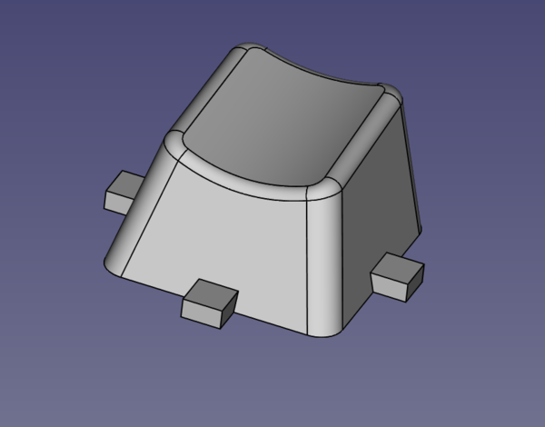
I reused the CAD model I did for the keycap CAD Dojo project (which I've got a lot more mileage out of than I expected!), but modified to have some retention tags around the perimeter:
Rendering a depth map
With the CAD model exported to STL, I wrote a Perl module to software-render STL files into a depth map. Rasterising triangles is easier than I thought it would be. For each triangle in the object, you just need to:
- draw the 3 lines that define the edges of the triangle, remembering the minimum and maximum x coordinate for each y coordinate
- draw a horizontal line for each y coordinate, from minimum to maximum x coordinate
And then you've drawn all of the triangles in a single colour. To draw a depth map instead of a single colour, you need to colour each pixel based on the z coordinate in the STL file. You can calculate the z coordinate of each pixel on the edge of the triangle by linear-interpolating between the 2 vertices that define the ends of the edge, and you can calculate the z coordinate of each pixel on the horizontal lines by linear-interpolating between the 2 points that define the left and right hand edge of the horizontal line.
Since there can be more than one triangle that covers a given (x,y) coordinate, and we're trying to draw the view from above, we need to make sure that we only draw the depth of the topmost triangle into each pixel. Your first thought might be to sort all of the triangles by z position, but this actually doesn't work because this is not a well-defined ordering, because triangles have one z coordinate for each of the 3 vertices. The way this is typically done in computer graphics is to have a separate depth buffer (basically a whole separate image that draws a depth map instead of the real colours), and write the z coordinate of each pixel into the depth buffer, and only plot a pixel when the new z coordinate is higher than what is already in the depth buffer. Since we're only trying to draw a depth map, we can use the main output image as the depth buffer itself.
So then the algorithm for plotting a given colour at a given pixel is just to check whether the new colour is brighter than what is already there, and only draw the new colour if it is. And then we've succeeded in drawing a depth map of an STL file.
I added a flag to make it draw the depth map from the bottom instead of the top, so that we can machine the bottom side of the part separately, and after getting the output image I modified it in Gimp to create 4 identical copies of the part, and to reduce pointless cut depth around the edge of the part on the bottom side (since this will already have been cut out from the top side operation).


Hopefully you can understand what you're looking at here. Brighter pixels represent higher z coordinates, so on the top depth map you have mostly-white in the middle (with a slight curvy gradient), and then quite steep drops towards black at the edges.
These are then turned into G-code with pngcam.
(Those are the exact depth map images I used, so if you wanted to replicate this, you could download those and make some yourself; it could also be used to make wooden keycaps although I have not tried that yet).
Machining
Here's a video showing the machining process, but it's quite long and boring:
All of the operations on the top side used a 4 mm ball-nose end mill. This is relatively easy. Clamp the material down however you want, set the Z axis 0 position to roughly the top surface of the material, and just run the G-code. Easy.
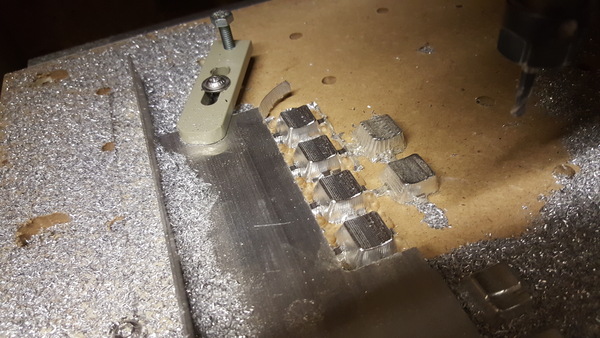
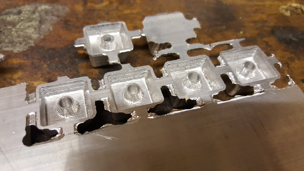
The problem comes when you need to flip the part over to machine the bottom side. In total I had 12 attempts at making keycaps, and only for the final 4 (machined as a single batch) did I manage to successfully align the bottom side with the top side. You can see some of the failed attempts still attached to the base material, from where I was too demoralised to even bother separating them.
The solution I settled on is to clamp down a straight edge parallel to the X axis and reference one side of the material to this straight edge. That means when we flip the part over, we can easily return the material square to the table, and we retain the Y coordinate for free. I also made sure to drill a hole at a known position from the top side before unclamping the part, and then pick up this hole on the bottom side after clamping it down, to act as a new reference for the X coordinate.
This works but you need to make sure that the straight edge can't move when you unclamp the part, and you need to make sure that you know exactly the relationship between the position of the reference hole in your top-side and bottom-side coordinate systems.
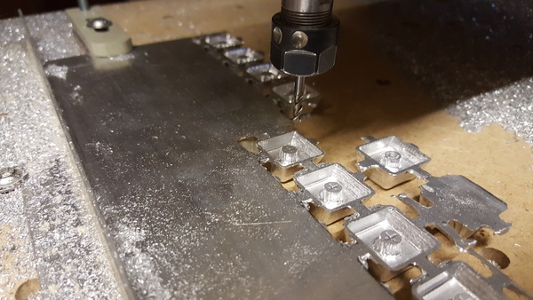
The bottom side was roughed out with the 4 mm ball end mill and then finished with a 2 mm ball end mill because the 4 mm tool won't fit in all the gaps properly.
Finally, because I don't have a tool thin enough to cut the 1 mm cross shape to attach the keycap to the switch stem, I bored out a 4 mm hole which will be useful later.
Finishing
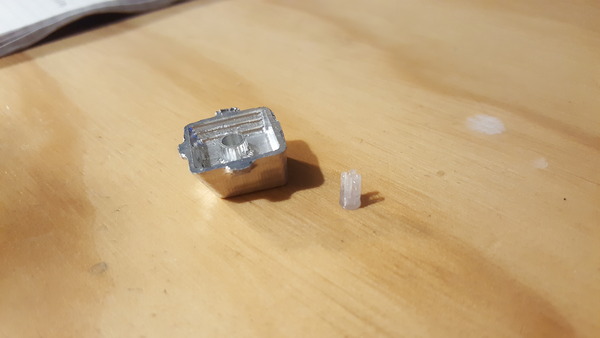
To make the keycap presentable, I first filed off the retention tags, then sanded down the tool marks starting from about 160 grit sandpaper and ending at 2000 grit, and then polished it with Autosol. I think I went up through the grits a bit too fast as there are still some visible sanding scratches, but it's good enough to satisfy me.
And this is how I'm going to fit the keycap on the stem. A 3d-printed plastic insert that has the cross shape in it, and fits inside the 4 mm hole.
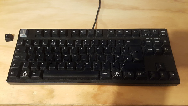
(The keyboard definitely looked less dirty in real life than it does in the photo).