
Since my Wig-Wag has run in a bit now, I have revisited the loss calibration.
Measuring RPM
Last time, I measured the engine speed by measuring the time between the pulses in the audio track of the video.
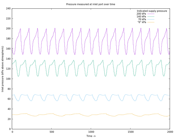
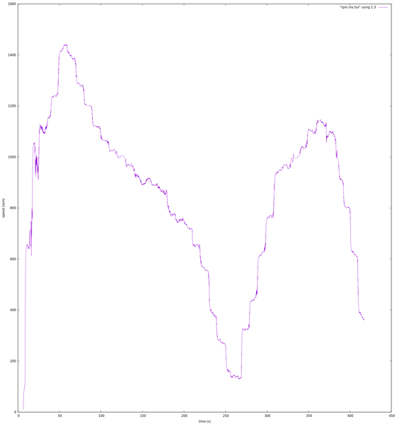
I'm now measuring it with the inlet pressure sensor! This is possible because the pressure drops when the port opens, so you can look at the frequency of the resulting waveform to work out how fast the engine is running:
My first attempt at this was to write some stupid ad-hoc code for peak detection and then work out the engine speed based on the time between peaks. This didn't work very well:
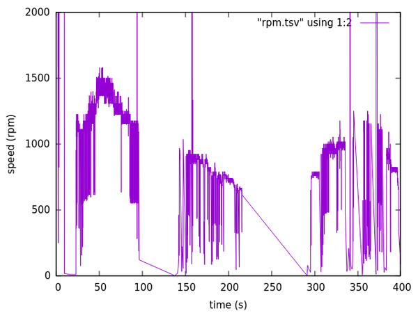
I think the data was too noisy for my stupid peak detection to work properly.
So next I tried taking the FFT of a sliding window of pressure readings and then saying that the frequency with the highest peak (within a sensible range) is the most likely engine speed. It sometimes picks up harmonics though (e.g. 2x or 0.5x the true speed).
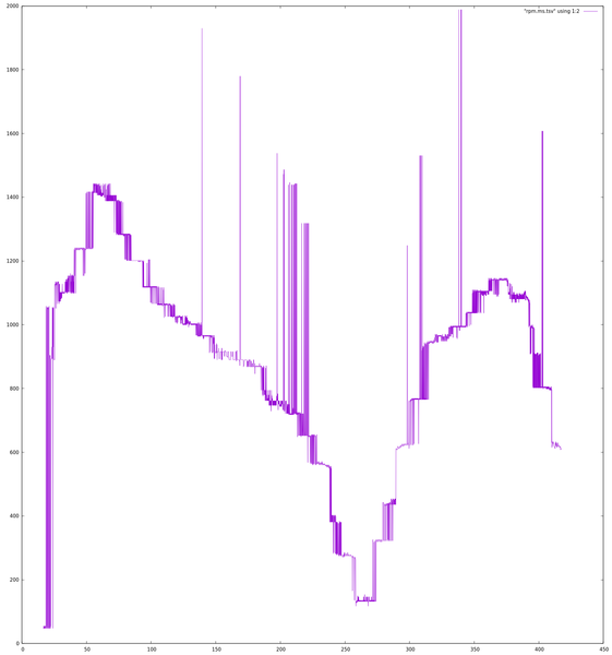
I solved this by manually adjusting the "sensible range" at different points in the data until all the harmonics seemed to be gone.
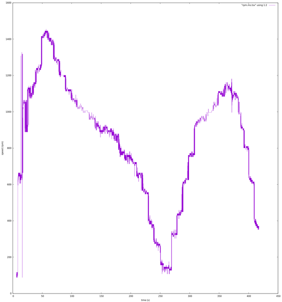
And finally, taking an exponential moving average of this data, we get the RPM plot that I'm treating as the "truth".
Working out RPM from the inlet pressure is good enough for this purpose, but I still want to use an encoder on the crankshaft to measure the crank position when I come to plotting pressure-volume diagrams.
Measuring supply pressure
Last time, I got the supply pressure from the number shown on the gauge on the compressor. I don't have a lot of confidence in that gauge, and now that I have the inlet pressure sensor I can use that instead. I'm saying that the supply pressure at any given time is the peak pressure from the inlet pressure sensor over the last 0.6 seconds. This is a long enough window that it covers a peak from the last cycle even at the lowest engine speeds.
So then we can draw a scatter plot of speed-vs-pressure from every datapoint:
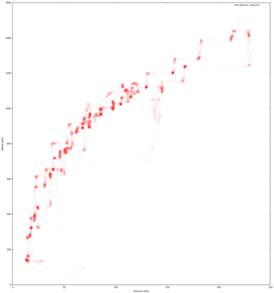
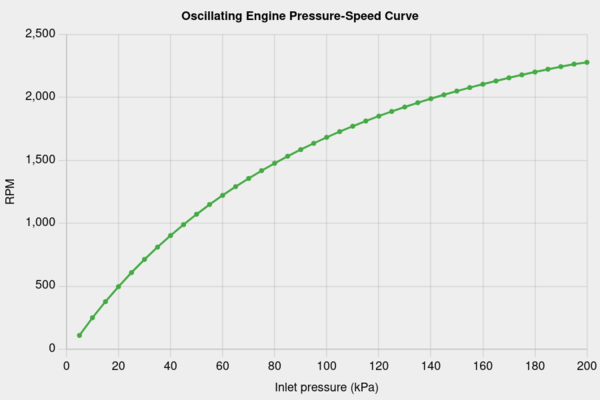
It is a bit noisy, but it does follow the form of the theoretical relationship:
Loss calibration
Armed with a representative sample of speed and pressure datapoints, I manually adjusted the loss torque in the simulator until the simulated engine speed matched the real engine speed for the same supply pressure (this time also using the "reservoir" supply model I described in "More inlet pressure measurements").
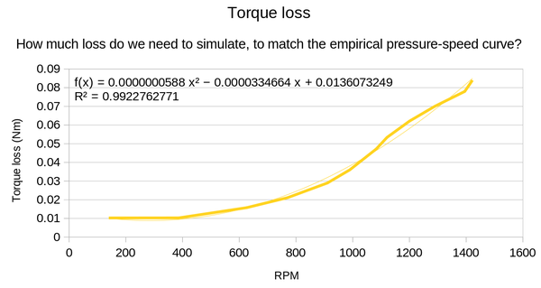
Here's the old vs new loss calibration curve:
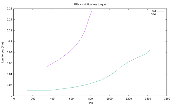
(I don't know why the new line is wiggly - I'm guessing it's caused by uncertainty in where exactly the "true" curve runs from when I picked samples from the speed-vs-pressure scatter plot).
Because the engine now runs more freely, it can both run slower without stalling and run faster on any given supply pressure. So the range of recorded speeds is larger, and the friction is lower at all speeds.
And here's the quadratic fit from LibreOffice:
In light of this, I've added support for a quadratic loss model to the simulator.
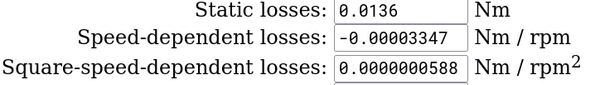
I don't know if that UI is really the best way to represent it. Maybe I should make it clearer that the values are coefficients of a quadratic function.
And here's the scatter plot from above (red), with the measured speed-vs-pressure curve from the simulator (green), using the quadratic loss model:
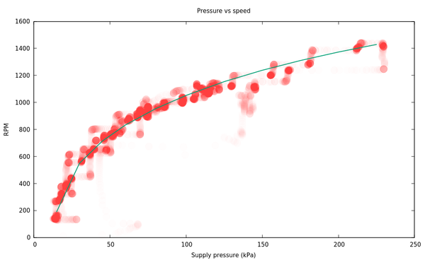
That's close enough for me!
Engine modifications
Now that the loss model in the simulator might be reasonably close to reality, I wanted to simulate some engine modifications to see if we can find improvements on the standard Wig-Wag configuration. All of these cases are with 200 kPa supply pressure (= ~30 psi).
(Note all the following are using a simulated version of my actual engine, which means the bore is 15.2mm, the gap above piston at TDC is 8mm, and the piston+rod length is 61mm).
Firstly, if we were to drill out the cylinder port, would we be able to improve efficiency, power, or both?
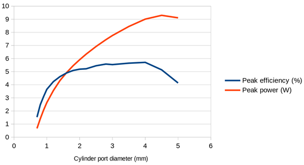
The standard cylinder port is 2mm. We can improve both peak power (by about 50%!) and peak efficiency by drilling this out to maybe 4mm. (Though note that peak power and peak efficiency are not achieved at the same speed).
What about if we left the cylinder port as standard and drill out the inlet/exhaust ports instead?
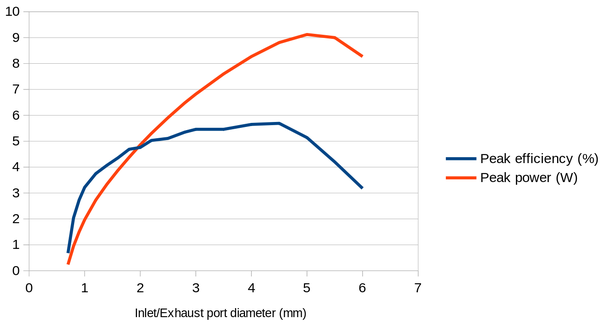
The standard inlet/exhaust ports are 2.5mm. We can improve both peak power and peak efficiency by drilling these out to about 4.5mm.
And finally, what if we drilled all 3 (to a single size)?
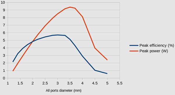
Somewhere between about 3mm and 3.5mm looks best.
So it should be pretty easy to get about 50% more power out of a Wig-Wag at 200 kPa just by tactically drilling out some/all of the ports. I don't want to make any modifications to my actual engine until after I have managed to plot some pressure-volume diagrams from it, so my next move is probably to put a threaded hole in the top of the cylinder and fit the pressure sensor to the cylinder, and make the crank position sensor.