
I have bought a "6040" CNC router, and have been getting to grips with how to use it. This journey started with converting the machine to Grbl because I'm not interested in running proprietary software. Once Grbl was all working correctly, I clamped a small piece of plywood to the bed, fitted a 2mm end mill and made my first cuts, manually "jogging" the tool position using the buttons in the UGS interface.
I have this video clip of what happened, but it was basically uneventful and worked fine! This is what I ended up with:
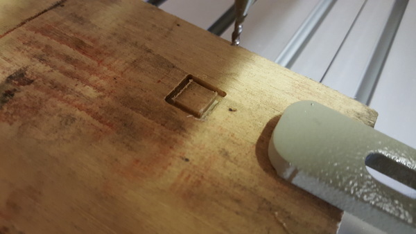
Great success!
Generating toolpaths
Now that I'm clearly an expert at operating the machine, it was time to fire up FreeCAD's Path workbench and generate some G-code. I modelled this part:
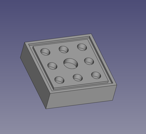
Although at this stage I couldn't work out how to generate a toolpath for the square pocket around the edge, so I only ended up cutting out the circular holes. This worked, but it was a very rough cut:
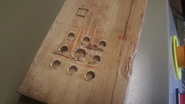
I have this video of it. You can see that it took a pretty aggressive bite, which I think is why there is so much tear-out around the edges of the holes. I learnt that for next time I'll need to go into the tool settings in FreeCAD and turn down the feed rate.
Making a part from CAD
At this point I wanted to try cutting some aluminium, so I modelled a more realistic test part and generated toolpaths for it.
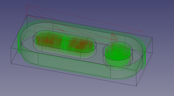
(This is the toolpath I eventually settled on, with very small step down, not the first one I tried).
You might have to zoom in to properly see the toolpaths, but you should be able to see that this time I generated a facing cut on the top surface, a hole all the way through with a step at the bottom, and a slot that only goes to half the depth.
You can also see that with the outer profile I have left some "tags" of material in place (the path moves up and then down to leave a triangle shape behind). This is so that the part does not break loose towards the end of the cut. These tags are then broken by hand to free the part from the stock it is cut out of. These are added by a toolpath "dressup" in FreeCAD. There are quite a few dressup types available, they all work by taking in a path that has already been generated, and modifying it in some way (here, by making it avoid the locations of the tags).
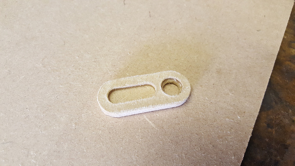
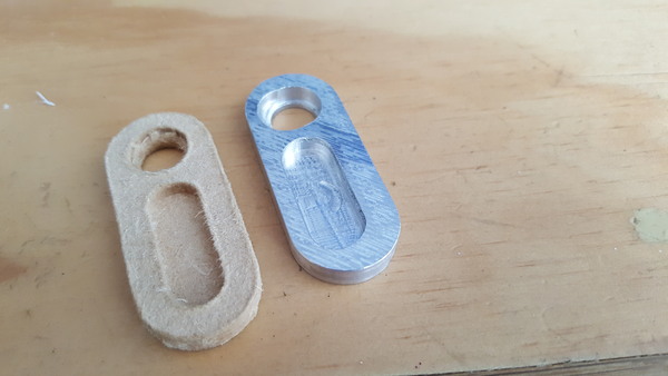
I was still afraid to try aluminium, so I started by cutting this part out of MDF. It went quite well and I got this out:
It seems a facing cut is not a sensible thing to do to MDF, but it cleaned up OK with a light sanding:
Aluminium
There's no point procrastinating any further: it's time to clamp some aluminium down and see what happens. I have this video of what happened. To cut a long story short, I got about this far before the end mill broke:
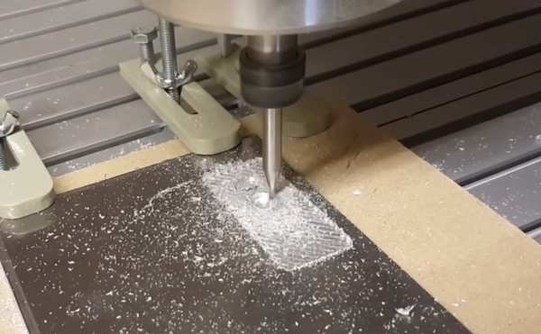
This was actually quite encouraging, because it showed that the machine is perfectly capable of cutting aluminium, which is what I was most concerned about. I think the end mill broke because I was still taking too large a cut, and also I was using one of the "free" end mills that came with the machine, so I have no idea what kind of quality to expect from them, or if they are even suitable for aluminium in the first place.
FreeCAD seems to default to using a "step down" of 100% of the tool diameter. That seems like quite a big ask for a 2mm tool, so after observing this failure I reduced the step down to only 20% of the tool diameter, or 0.4mm per pass.
Having regenerated the toolpaths with a reduced step down, I attempted to realign the tool with the (0,0,0) point on the work, and then try again. The cutting worked great, although I did not get the alignment very close, so the features cut by the 2nd attempt do not line up very well with the features cut by the first attempt.
I also found that about 30 minutes in, the machine stopped moving completely and UGS reported that it was disconnected from Grbl. This was a bit concerning. I looked in dmesg and found that Linux suspected EMI was the cause of the disconnection. I had this problem once before while setting up Grbl and found it went away when I moved the computer further away from the control box, so this time I just moved the USB cable away from the control box and tried to reconnect and it worked fine. Now that I've got the control box in a more permanent location, I have the USB cable on a relatively taut run directly away from the box, and I haven't experienced this problem again.
This time I didn't move or reset anything, so I thought I would not need to realign the tool to the work because UGS still thought it knew where the tool was. Unfortunately this didn't quite work and I ended up a couple of mm away from where it should have been, thus introducing a 3rd set of features not aligned with either of the previous two. Oh, well.
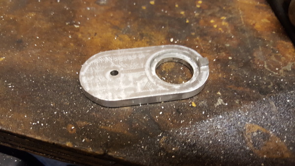
I deleted all the G-code that I was confident had already been executed, and sent the rest, and the part completed with no more failures! Great success, ish. After filing off the tabs left around the edge, this is what I got:
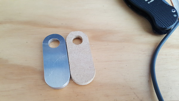
I'm mostly pleased with this, although I would have been more pleased if all the features on the aluminium part lined up with each other.
Puzzle design
Now that I'm obviously an expert at both operating the machine and generating toolpaths for it, and have demonstrated my prowess in machining parts from aluminium, it's time to make something "useful". I have 3d printed quite a lot of puzzles based around the idea of extracting a trapped coin, so I thought I'd start with one of those. This particular puzzle is a clone of the "penny pincher" puzzle. I think I first saw the idea on a YouTube video from a Maker Faire, but I can't find that one now. You can see an example of the idea in this video.
It has 3 levels that can all pivot around a bolt. The coin is trapped in a recess in the bottom level. To remove the coin you need to rotate the middle level away from the bottom level, but it is prevented from rotating by a peg in the bottom level that engages a slot in the middle level. So you need to move the middle level horizontally before it will rotate, but it is prevented from moving horizontally by an unseen ball bearing that hits against the pivot bolt. So you need to tip the puzzle upside down to allow the ball bearing to move into a recess inside the top level, and then you can rotate the top level away, which will then allow the middle level to slide horizontally, which will then allow the middle level to rotate, allowing the coin to be removed.
Ideally it would be impossible to slide the middle level until the top level is rotated, but since I'm relatively new to this I kept life simple for myself and made the middle and top levels perfectly flat. Here's the CAD:
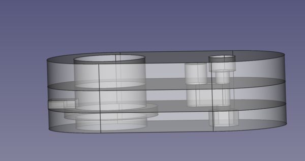
Hopefully you can understand how it works if you follow along with the description above.
The thickest aluminium sheet I have is 6mm, which means the top level of the puzzle can't be any taller than 6mm, which means the ball bearing has to be smaller than this. I didn't have one suitable, but I proceeded anyway and have ordered some 4.5mm ball bearings.
Each of the 3 parts can be completely machined from just 1 side, except for the pockets for the bolt head and nut. This is good because it means I can test everything with only 1 setup per part, and then come back and make the pockets in a second setup, after I know everything else has worked.
Having learnt from my difficulties in aligning the tool with the work before, this time I made sure to put the origin on the axis of the bolt hole, so that I can always pick up the centre again by jogging the machine so that the tool lines up with the bolt hole on the part.
Making puzzle parts
I clamped down some aluminium, zeroed the Z axis on the surface of the metal, and just as I started jogging X and Y into position, the end mill broke. I hadn't even started cutting anything! I think my "zero" of the Z axis was a bit more aggressive than necessary and the tool was actually pressed into the metal slightly when I was trying to move it in X and Y. D'oh!
I didn't have any more 2mm end mills, so I chucked up a 3mm end mill instead and went back to FreeCAD to regenerate all my toolpaths. This time I moved the Z axis away from the part before moving X and Y, which worked a lot better.
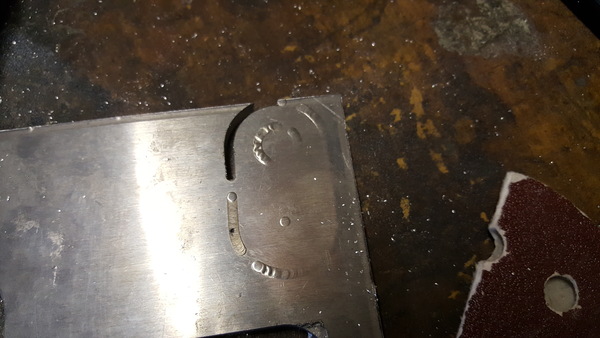
I don't have a lot of photo or video from this, because I was busy concentrating on not messing it up, but it mostly went well, with no more broken end mills and no disconnection due to EMI. The biggest mistake was that the toolpaths for the slot in the middle piece and the "peg" on the bottom piece left rounded corners instead of straight sides, because the generated toolpath attempted to trace the outline of the flat top area, without knowledge that the sides of it are empty space and can be safely cut into:
I fixed this by operating the tool manually, using the GUI, but I'm not entirely sure what would be the best way to generate toolpaths to do this, maybe do the "adaptive" process like this followed by a "profile" around the outside of the peg?
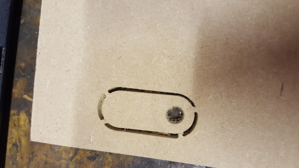
With all the machining done, it's time to break the parts out of their base material. Some of them didn't quite cut all the way through, leaving a thin foil of material:
This was easily broken through, but I'd have preferred to make the tool cut slightly into the wasteboard rather than leave material on the part.
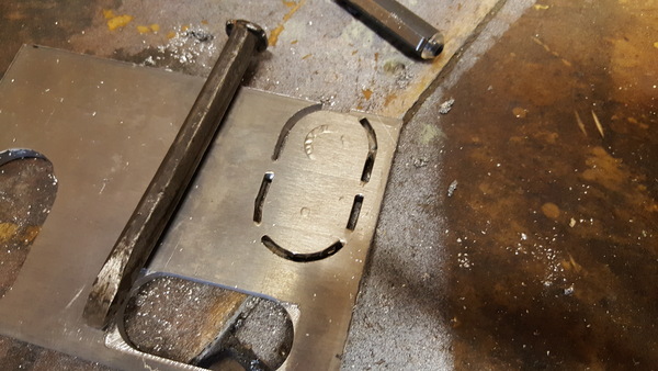
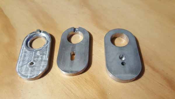
I broke the solid tags with a hammer and chisel, and then we have to tidy up the edges:
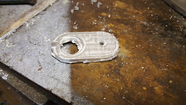
Most of the flashing is easily removed, and then it's just a case of filing the tags down, and a light sanding to disguise the apprentice marks:
Repeat this for each part:
And bolt the puzzle together:
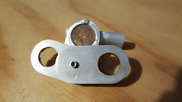
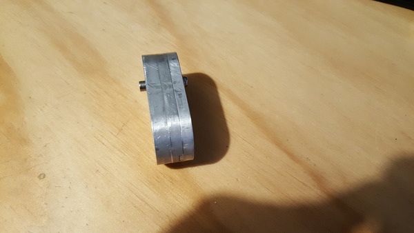
Great success, everything fits. The edges are not very neat, I will try to use tags more sparingly in future.
Enclosure
At this point I built an enclosure for the machine, primarily to stop it spraying aluminium shavings all over my garage, but also to keep the noise down a bit, and protect the machine from welding and grinding sparks in the future. I wanted to make the whole thing out of perspex, but perspex is surprisingly expensive, especially in large sheets of a decent thickness. So instead I made it out of materials I already had on hand.
It's not very well made, but it should do the job.
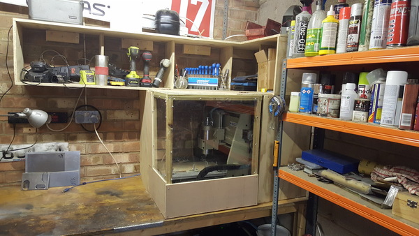
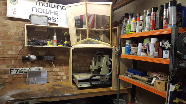
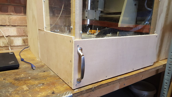
The idea is that when the door is closed I can still see what's going on inside through the window, and when the door is open I have unimpeded access to the inside. I thought I had a spare handle lying around which I wanted to use, but I couldn't find it. James generously supplied me with a free kitchen cupboard door handle:
Puzzle parts, 2nd setup
It's tempting to stop here, given that the puzzle works (or at least, it would do, if I had a ball bearing that would fit inside). But the point here is to learn a bit about how to make parts with this machine, so let's proceed.
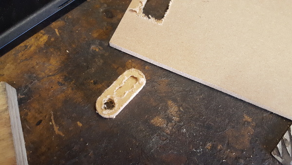
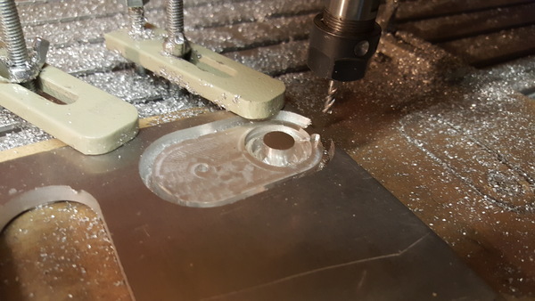
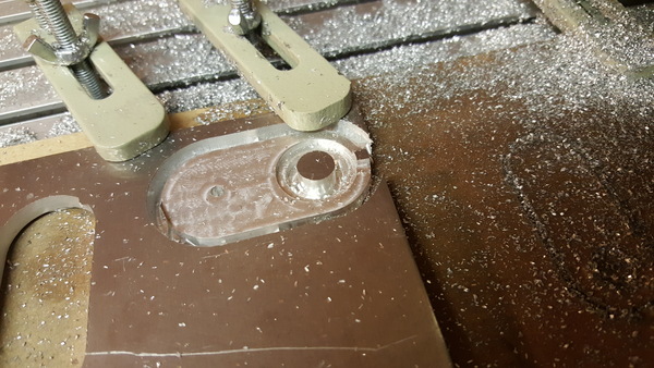
To mount the bottom puzzle piece upside down on the wasteboard, I first cut a small pocket out of it "manually" so that the raised peg can sit down into the board. I could have had the peg overhanging the edge of the board, but I couldn't be bothered rejigging the hold-down clamps, and this way seemed more interesting:
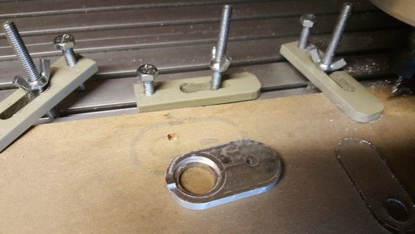
I then manually aligned the tool with the centre of the bolt hole:
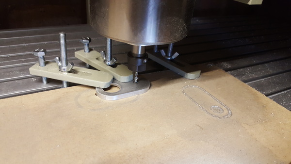
And ran the G-code to get a hexagonal pocket for the nut. I did take a video of this step, which also shows a bit of operating UGS and showing how the enclosure opens and closes. The result is this:
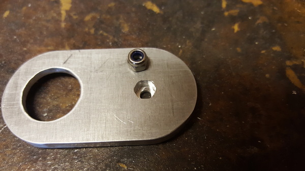
I wasn't sure if I'd need to come in again with a dogbone dressup to make the nut fit in the hole, but this wasn't necessary and it was easy to press-fit the nut using the vice:
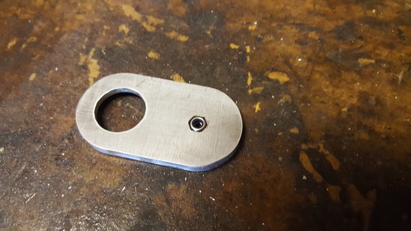
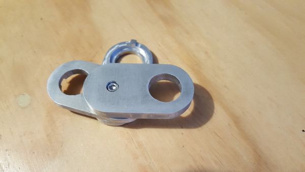
A similar setup is used to make the circular hole for the head of the bolt, and the whole thing can be put together:
UGS
So far I have only been using UGS "Classic". This is because I was initially unable to get UGS "Platform" to work on my laptop. It segfaulted on startup, even when using the version that bundled a presumed-working version of Java. I have since replaced Ubuntu 18.04 with 20.04, and now UGS Platform works fine. I've connected it up and jogged the machine around to test it but have not yet ran any G-code with it. UGS Platform appears to be a substantially superior program, it gives you much more control over the machine and also includes a visualisation of the toolpaths.
I think it would be handy to have a plugin in UGS that would quickly generate and run paths for simple operations like circular holes, square holes, slots, etc. so that I can more easily make quick changes to a part without having to go all the way back to FreeCAD. That said, I looked at the UGS development documentation, and it seems very Java, so perhaps I won't do it. It might be almost as handy to just have an external program write a G-code file which can then be loaded in UGS, and probably something like this already exists.
Comparison to 3d printing
The CNC router is not nearly as convenient as the 3d printer. Compared to the 3d printer, the router requires:
- hand-holding in toolpath generation
- base material of sufficient dimensions to contain the part
- end mills of appropriate shape, size, and material
- clean up of chips at the end
- manual finishing to separate the part from the stock
Whereas the 3d printer can print all part geometries out of the same spool of base material, can make all feature shapes using the same nozzle, doesn't create any waste material (modulo support structure), and toolpaths are automatically generated by the slicer.
However, the CNC machine has the big advantage that it can make parts out of a wider range of materials, it can make much bigger parts, and it gives finer control over the surface finish.
I think for small parts where plastic is acceptable, 3d printing is definitely the way to go just because it's so easy.
Remarks on the 6040 CNC machine
I am pleasantly surprised by the machine. It came almost completely assembled, which made putting it together a doddle, and it is much sturdier than I expected, but there are a few things that I think could easily be improved:
The hold-down clamps are very poor. The bolt that slides in the T-tracks on the bed is just a normal hex-head bolt and is not large enough to prevent the head from rotating. I have developed a technique of holding the loose end of the bolt with a pair of pliers while I tighten or loosen the wing nut, but they should have just supplied proper T-nut bolts. I'll probably replace them.
The text on the front panel for spindle speed control has "PC" and "Manually" modes, surely this should say "Manual" instead of "Manually". Similarly, the labelling on the back panel for the spindle power says "SPANDLE". Given how popular the machine is, it seems totally implausible that nobody involved with it speaks English well enough to spot these mistakes, so I wonder why they still haven't been corrected?
The stepper motors have knobs on them that would appear to allow for easy manual operation, but the stepper motor drivers are wired from factory so that the steppers are always switched on (and therefore holding position) whenever the machine is powered on, which means the only time you have a chance of manually turning them is when the machine is switched off so you can't cut anything. Surely either make it so the steppers are easily switched off, or don't bother adding a manual knob to the back of each one?
That's nitpicking though, really. It's a great machine, much more capable than I require.
Lessons learnt
I found that I got a decent cut in aluminium with a 3mm 2-flute carbide end mill with a feed rate of 200 mm/min, step down of 0.4mm and step over of 0.4mm. From first principles, I think I would extend tool life by increasing the step down and decreasing the step over, on the basis that I am currently only ever using the bottom 0.4mm of the tool height. Perhaps I should experiment with this. I also wonder if there is a reasonable DIY method to grind off the bottom 0.4mm of a worn-out tool so that I can get a sharp edge again, comparable to sharpening a drill bit? Might be worth looking into.
I need to manually start the spindle before sending G-code, because it takes a long time for the VFD to spin the spindle up to top speed. Maybe I could reconfigure the VFD to spin up faster, but the documentation is sorely lacking. If you just send G-code without manually waiting for the spindle to speed up, then it might plunge into the work before reaching the required speed.
I sprayed water and WD-40 on the first cuts I did in aluminium under the belief that it would need some cooling, but I found that this only serves to gum up the chips and keep them from getting away from the tool. I did the later parts with no part cooling and the part didn't heat up noticeably, and the chips cleared the cut more easily, so I probably won't be using coolant on aluminium.
I should tell FreeCAD to cut a bit deeper than the required thickness of the part so that I don't have to manually peel away a thin foil of aluminium left on the bottom.
I should use tag dressups sparingly because they are hard to remove neatly, and leave a poor surface.
The USB cable should be kept as far away from the control box as possible, to reduce electromagnetic interference.
It is helpful to have a plan for how to realign the tool with the work. Even if the part can be made in a single setup, something might go wrong and it might require realigning, so it's helpful to be able to do it accurately.
If the Z axis is zeroed before X and Y, I should move the Z axis back up before trying to move X and Y, lest I scratch the top surface in the best case or break the end mill in the worst case.
Still to learn
I don't know how to calculate what speed I should run the spindle at. So far I have been running it at full speed of 24,000 rpm because I read that it produces the most power at the highest speed. I also read that for cutting metal you generally want lower rpm, so I don't know which of those 2 properties takes precedence. It is not obvious to me that spinning the tool more slowly is going to help anything, seems like it could only hurt.
I don't know how to get FreeCAD to rotate the job to let me work on the "bottom" face of the part. So far my only solution is to manually rotate the part itself and then use the Path workbench to generate toolpaths on the new top face. Seems like this is pretty basic though, so the Path workbench probably supports it, I just need to find out how.
I don't know how to get the generated toolpath to run into empty space at the side of a feature where I want square edges instead of rounded edges. Again this seems pretty basic so is probably possible, just something I need to learn. I think in the worst case I could manually edit the generated G-code to extend the path in the relevant places, although this seems error-prone.
That's all I have to say about my adventures in CNC machining so far. If you can help, or have any comments, please get in touch.