
Composite kitchen worktop material is a good choice for a CNC machine because it is very heavy and very flat. It is a bad choice because it is quite soft. But mainly it is a very good choice because I already had the material and it is therefore free.
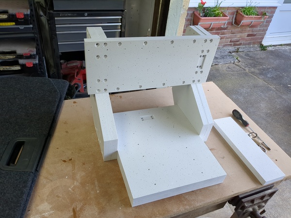
So far I have cut out all of the kitchen worktop parts, and I've epoxied together the plates that need to be doubled-up. Next up is fitting threaded inserts, then bolting all the hardware on and getting it hooked up to the electronics. Hopefully not an awful lot of work left to do.
Motivation
I'm building this machine because I have been dissatisfied with both my 6040 CNC machine and my CNC-converted mini mill. The 6040 is not rigid enough to do a good job in metals, and the mini mill is not accurate because of the dovetail ways. Maybe you could sort out the dovetail ways by hand-scraping, but that is much too much trouble for me. So I have taken the mini mill apart, and for the new machine I'm going to reuse the mini mill's motors, ballscrews, ballnuts, control cabinet, enclosure, and flood coolant setup. So that is also a big cost saver.
I am hoping to be able to use the machine to make watch parts more effectively, although I am slowly learning that watchmaking is very difficult and I'm not very good at it, so it may end up being more of a clock.
Design
The table is 300mm by 200mm, and the X/Y motion range is the same. The Z axis has 150mm of motion, and the motor can be manually slid up/down in the clamp to change the location of that 150mm range (but note that tall objects will hit the gantry if you need a lot of Y range as well).
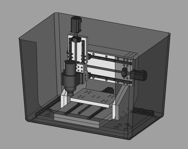
Here's a picture of what it will look like inside my "hotel laundry basket" enclosure, with hardware fitted:
I laid out my "Minerva" kitchen worktop offcuts in FreeCAD, and then laid my machine frame parts on top of the offcuts, so that I could work out how to make efficient use of the material I had available:
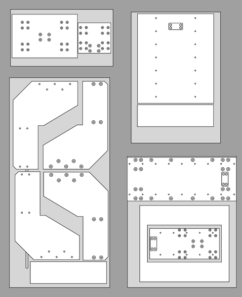
This obviously went both ways: where the parts didn't fit on the material I needed to make them smaller, and where I could see unused material then I could make the parts chunkier.
I also used FreeCAD's FEM workbench to do some simulations to work out where the machine was too floppy and beef up those sections. The main things I learnt were that doubling up the baseplate is a good idea, and doubling up the upright pieces is more effective than adding stiffeners at 90 degrees.
Here are some screenshots from FreeCAD, viewed from above, the first one shows perpendicular stiffeners on the uprights, and the second one shows the uprights doubled up:
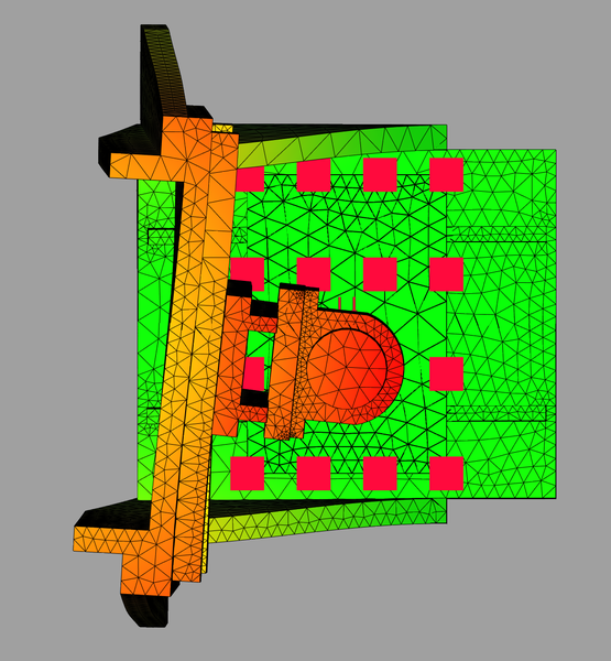
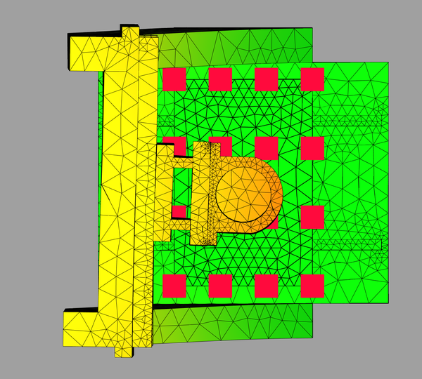
(This was simulating a 1000N force pushing the tool in the negative X direction, which is towards the bottom of the image, and the deflection is amplified by 500x to make it easier to see).
You can see that the deflection is much lower in the second case. This surprised me. I think the reason is that the sideways deflection at the tool doesn't come from bending the uprights to the side, it comes from twisting them forwards/backwards.
I setup the simulation using a datasheet of performance properties of Corian, because that is the closest material I could find to the "Minerva" that I have. But I'm not too bothered about the actual numbers, I was just trying to make it as stiff as I could with the material I had available. The purpose of the simulation was to avoid blunders, not to hit any specific numbers.
Threads
I was hoping to be able to tap threads directly into the composite material and bolt the parts together that way, but I could not find a way to tap convincing threads. They stripped relatively easily with only a medium gronk. I tested things like drilling the hole slightly undersized, using an undersized tap, and a range from M8 to M12 threads. Here are some of my test holes:
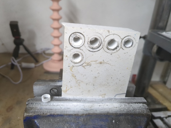
You can see sitting on the jaw of the vice there are several coils that sheared straight off without breaking!
So my solution for threaded holes is I have bought some threaded inserts and am going to epoxy them in place. They are steel cylinders with threaded holes up the middle, you could easily make them on the lathe if you were so inclined.
Other
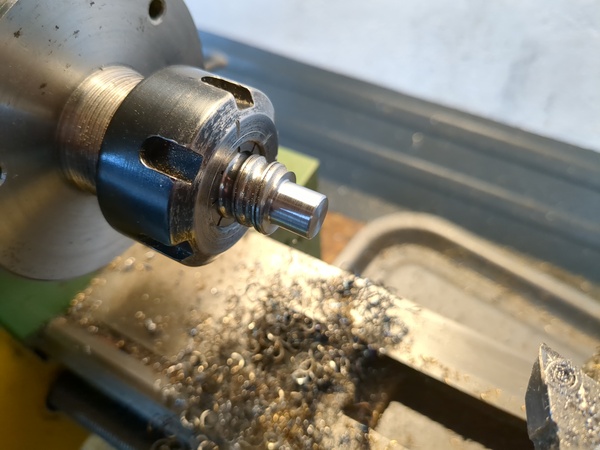
The ballscrews I took off the mini mill were longer than I needed, but I had good success cutting them short with an angle grinder and them turning down the ends on the lathe with a DCGT insert. These ballscrews are case-hardened, but the DCGT insert does a good job, and they are no trouble to machine once you're through the case-hardening.
It is common to use drag chains for cable management, to stop the cables getting caught in anything they shouldn't. But my X motor is fixed in place on the gantry, and my Y motor is fixed in place on the baseplate, so their cables can be fixed permanently. Then I only have the Z motor which moves left and right over a range of 300mm, and the spindle motor which moves left and right 300mm and up/down 150mm. So I am hoping to get away with running the cables to the Z motor and spindle motor through a "hook" that holds them directly above the centre of the gantry, and put enough slack in them to allow the full range of travel, but not so much that they can get snagged on anything.
The only parts I have needed to buy for this machine are the linear rails and carriages, spindle motor, and a VFD, plus minor parts like nuts and bolts, threaded inserts, bearing blocks, spindle clamp. I have spent less than £300 on this project and I nearly have everything I need. I have not yet bought a VFD, I'll do that once everything else is ready, because I can borrow the VFD from the 6040 to start with.
The spindle motor is a secondhand 2.2 kW water-cooled spindle motor, it was cheap because it leaked coolant, but I have fixed the leak.