
I have now used the 3d-printed light gate as a crank position sensor on the Wig-Wag, and the first impression is that it works well.
Slotted disc
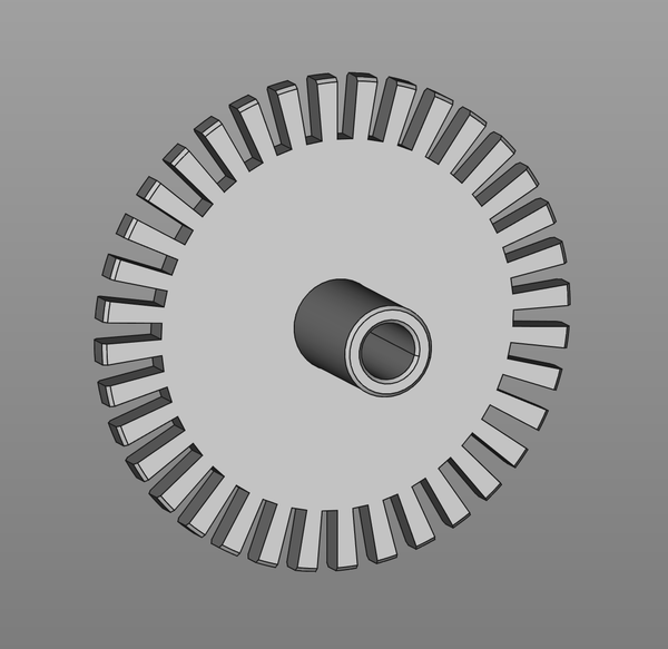
I modelled a slotted disc to intermittently block the IR light on the light gate. The disc has 36 slots, which means the resulting signal from the light gate will have 72 edges per revolution, so we can detect crank position in 360/72 = 5° increments.
I printed the disc in PC Blend, and fitted it to the crankshaft:
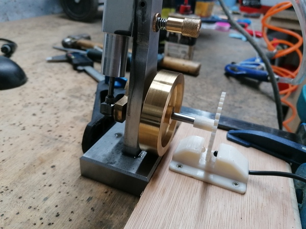
It's just held on with friction, but that's adequate. You can see a video clip of the engine running with the disc in place if you like.
One advantage of measuring the crank position this way is that it adds no friction to the engine. OK, maybe a tiny bit of air resistance. But if you were to connect a standalone rotary encoder you would be adding some friction, which could make a measurable difference to how the engine runs at low speeds under no load (which, after all, is the usual running condition for a model steam engine).
Datalogging
To collect data from the sensor, I wrote the stupidest Arduino program I could think of. The (analogue!) output of the light gate is wired straight to a digital input of the Arduino, and I'm just reading it in a loop with digitalRead() and outputting millis() to the serial port whenever the input changes.
This seems to work well enough, even without any signal conditioning. I was worried that the signal would sometimes flutter around the threshold and some debouncing would be required, but it doesn't look like it.
I do want to try reading the light gate with an interrupt instead of a loop. That should improve the precision of the timestamps, and means I get to find out about changes to the pin state even while the program is busy doing something else (for example, writing to the serial port or reading the pressure sensor).
It turns out that millis() is not really precise enough. At 72 steps per revolution, at 500 rpm we have 600 steps per second, which means there's only 1 or 2 milliseconds between steps, which doesn't give us a lot of precision on the rpm measurement (i.e. it acts like steps are either 1 or 2 ms apart, which would imply either 417 or 833 rpm, with nothing possible in between). So I should switch to micros() instead.
But with a bit of post-processing we can gain some precision by looking at the time taken between multiple consecutive steps (I made my script look at all steps within the last 20 ms). This does cause some unwanted smoothing. Using micros() would be better, I'll do that for next time.
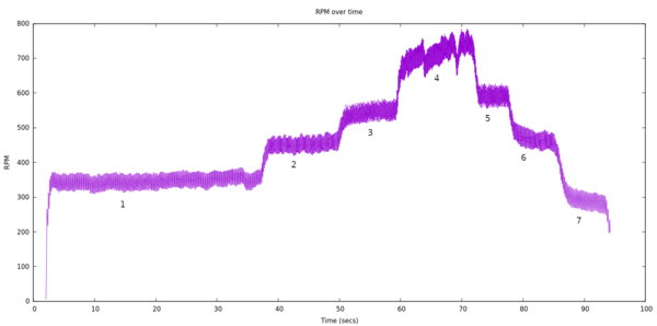
I have this plot showing the engine speed over time. It is labelled with 7 obvious separate "stages". These are caused by me manually adjusting the regulator on the air supply.
And this is the same data again, but a scatter plot of RPM against crank position:
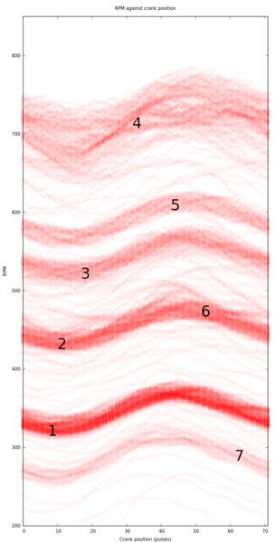
Hopefully that's easy enough to understand. During each revolution of the engine, the time is logged at 72 separate points. From the post-processing mentioned above, we turn the timestamp into the RPM at each of these points, and we know to reset the crank position to 0 every 72 points.
(Stage 4 is noisier because the engine speed varied more, consult the other graph; I think the engine was rattling a bit too much at this speed).
This shows what I really wanted to see, which is firstly that the speed varies throughout the cycle (i.e. the engine speeds up during the power stroke and slows down during the exhaust stroke). But most importantly it shows that the light gate is not substantially losing steps! Because the speeding up and slowing down is aligned extremely well to the 72-step cycle. This is good.
You can see that the peak engine speed is in roughly the same place during each stage, which means over the course of 90 seconds it can't have gained or lost more than a small handful of steps, which means it is probably viable as a crank position sensor.
Index pulse
If the sensor did gain or lose an important amount of steps, the solution I had in mind was to make some sort of "index pulse" that fires once per revolution, always at the same place. You could do this by putting a magnet on the flywheel and sensing it separately, or (easier) break off one of the teeth on the slotted disc and look for the longer pulse from the light gate. You'd then only get 70 steps per revolution, but one of them would be 3x as long.
A big advantage of having an index pulse is that it gives you absolute crank position. Without an index pulse, you know how many degrees the crank has rotated since you started watching, but if you don't know what position it was in when you started then you still don't know where it is at any other time. With an index pulse, you can turn your relative crank position measurements into absolute crank position measurements as soon as you've seen 1 index pulse.
So I think I probably want to add some sort of index pulse, just so that I get more confidence in the absolute crank position. Being able to re-synchronise once per revolution is an added bonus, although not apparently necessary. The big benefit is not having to manually synchronise when the logging starts.
Cylinder pressure sensor
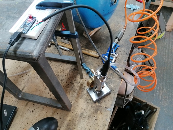
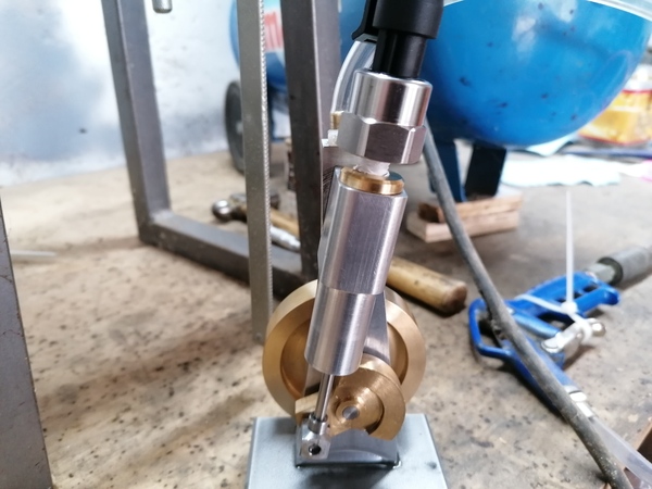
Before I did all the light gate stuff, I did also move the pressure sensor to the top of the cylinder. So now instead of measuring the inlet pressure, I'll get the pressure inside the cylinder.
I did this by putting a threaded hole in the brass part that plugs the top of the cylinder. The sensor is screwed down just far enough that the bottom of the sensor is flush with the bottom of the brass part, so I think it is not substantially affecting the volume inside the cylinder.
I did take some measurements from this and compared to the simulator:
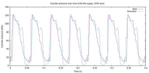
It's not a brilliant match; the simulator predicts a couple of sub-peaks that just don't seem to be present in the real data. Not sure what's going on there. Maybe the sensor (or Arduino ADC) doesn't react fast enough to changes in pressure? Maybe my sampling rate is not high enough? Maybe the simulator is wrong? Not sure.
But at least the speed and peak cylinder pressure sort of line up for the same supply pressure (which we'd expect, given the work I did on loss calibration).
Next
So I probably want to switch to using micros(), break off one tooth of the slotted disc, try out using the light gate to trigger an interrupt pin instead of reading it in a loop, and make it log cylinder pressure and crank position at the same time. Then I can finally try to reproduce the simulator's pressure-volume diagrams, which will be a really good milestone.